Fracturable lookup table and logic element

Inactive Publication Date: 2005-09-13
ALTERA CORP
View PDF50 Cites 81 Cited by
  • Summary
  • Abstract
  • Description
  • Claims
  • Application Information

AI Technical Summary

Benefits of technology

[0009]In one embodiment of the present invention, a logic element includes memory elements, multiplexers, and controls. The multiplexers are arranged in levels including a highest level of multiplexers with inputs connected to the memory elements and outputs connected to inputs of a next-to-highest level of multiplexers and a first level of multiplexers with inputs connected to outputs of a second level of multiplexers and at least one output. The controls are connected to the multiplexers. In a first operational mode the controls determine a first-mode output at the at least one output of the first level of multiplexers, and in a second operational mode the controls determine second-mode outputs at selected outputs of multiplexers not at the first level of multiplexers. According to one aspect of this embodiment, when the logic element is in the first operational mode, the first-mode output provides a complete function of the controls. According to another aspect, when the logic element is in the second operational mode, each second-mode output provides a complete function of a proper subset of the controls. According to another aspect, when the logic element is in the second operational mode, one or more controls are split into sub-controls so that a corresponding sub-control replaces each split control at each multiplexer connected to that split control. According to another aspect, the logic element further includes one or more control multiplexers with outputs connected to one or more of the controls of the logic element and with inputs determined by control-multiplexer inputs. Under some operational conditions, at least two of the control multiplexers receive an identical control-multiplexer input. According to another aspect, the logic element further includes additiona

Problems solved by technology

While mask programming may have disadvantages relative to some of the field programmable options already listed, it may be useful in certain high volume applications.
There is a tradeoff between cost and speed of a logic circuit constructed with LUTs.
Under these assumptions,

Method used


Image

  • Fracturable lookup table and logic element
  • Fracturable lookup table and logic element
  • Fracturable lookup table and logic element

Examples


first embodiment

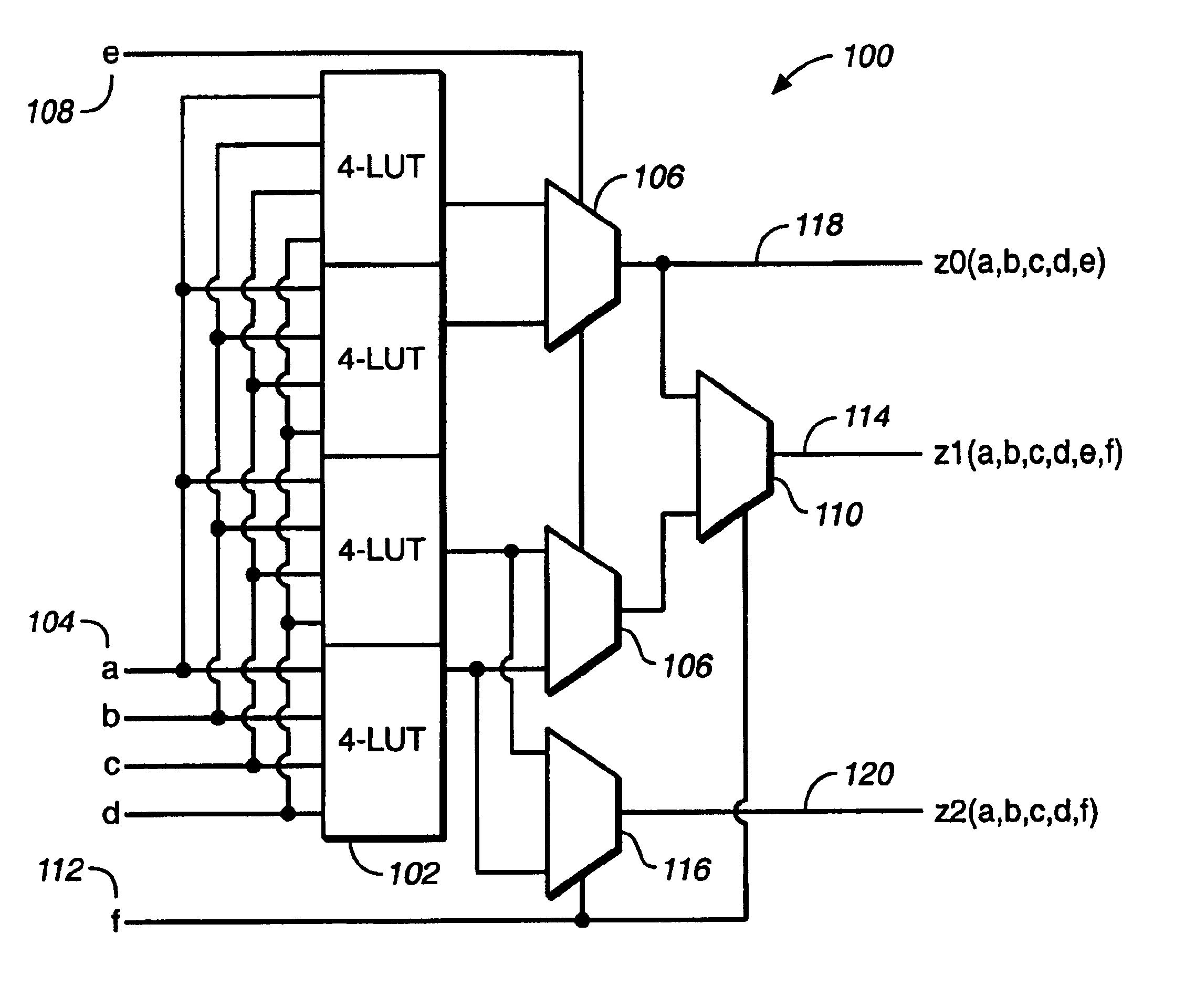
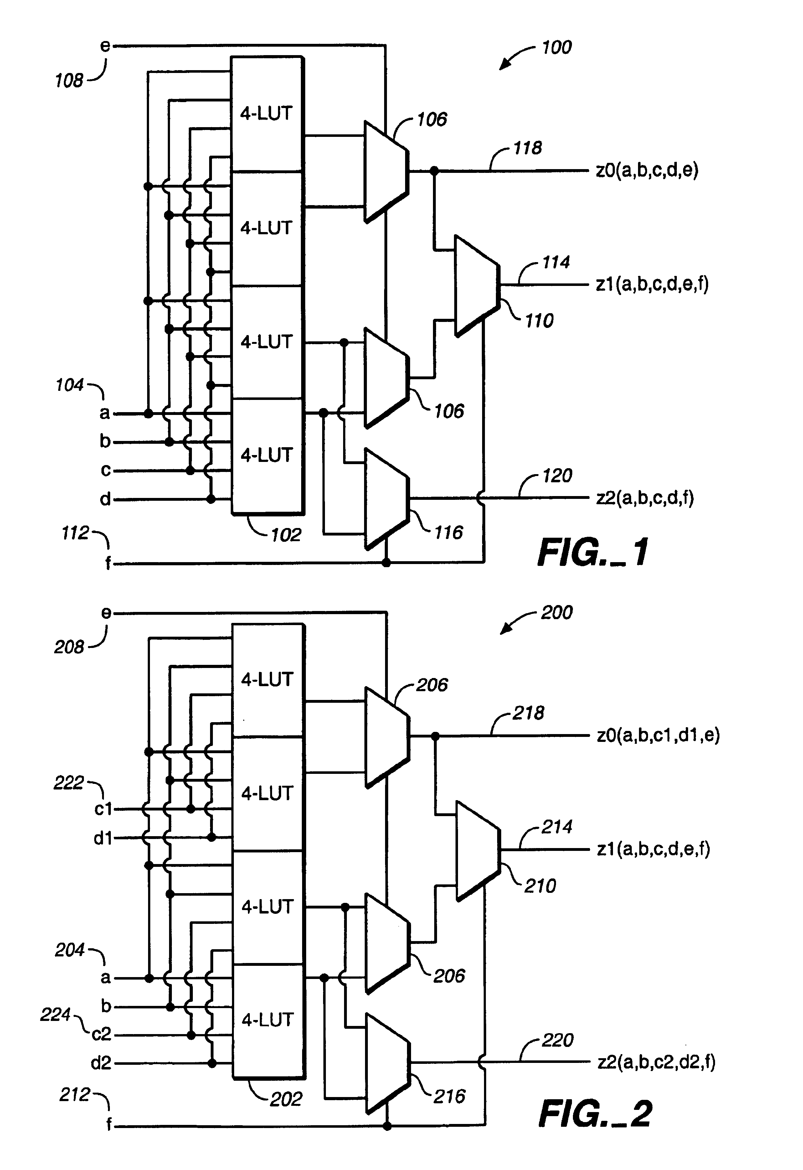
[0025]FIG. 1 shows a fracturable 6-LUT 100 according to the present invention. Similarly as in the conventional 6-LUT 700, the fracturable 6-LUT 100 includes four 4-LUTs 102. Each 4-LUT 102 includes sixteen memory elements and a 16:1 multiplexer that is controlled by inputs a, b, c, and d 104. Outputs from the 4-LUTs 102 provide inputs to two 2:1 multiplexers 106, each of which is controlled by input e 108. Outputs from these multiplexers 106 provide inputs to an additional 2:1 multiplexer 110 that is controlled by input f 112 to provide a final output 114. In this way any function of six inputs z1(a,b,c,d,e,f) can be implemented.

[0026]As compared with the conventional 6-LUT 700, the fracturable 6-LUT 100 includes an additional 2:1 multiplexer 116 that takes inputs from two of the 4-LUTs 102 and is controlled by input f 112. When used as a 6-LUT (i.e., in a non-fractured mode of operation), the output signal z1114 is a complete function of all 6 inputs. When used as two functions (i...

embodiment 300

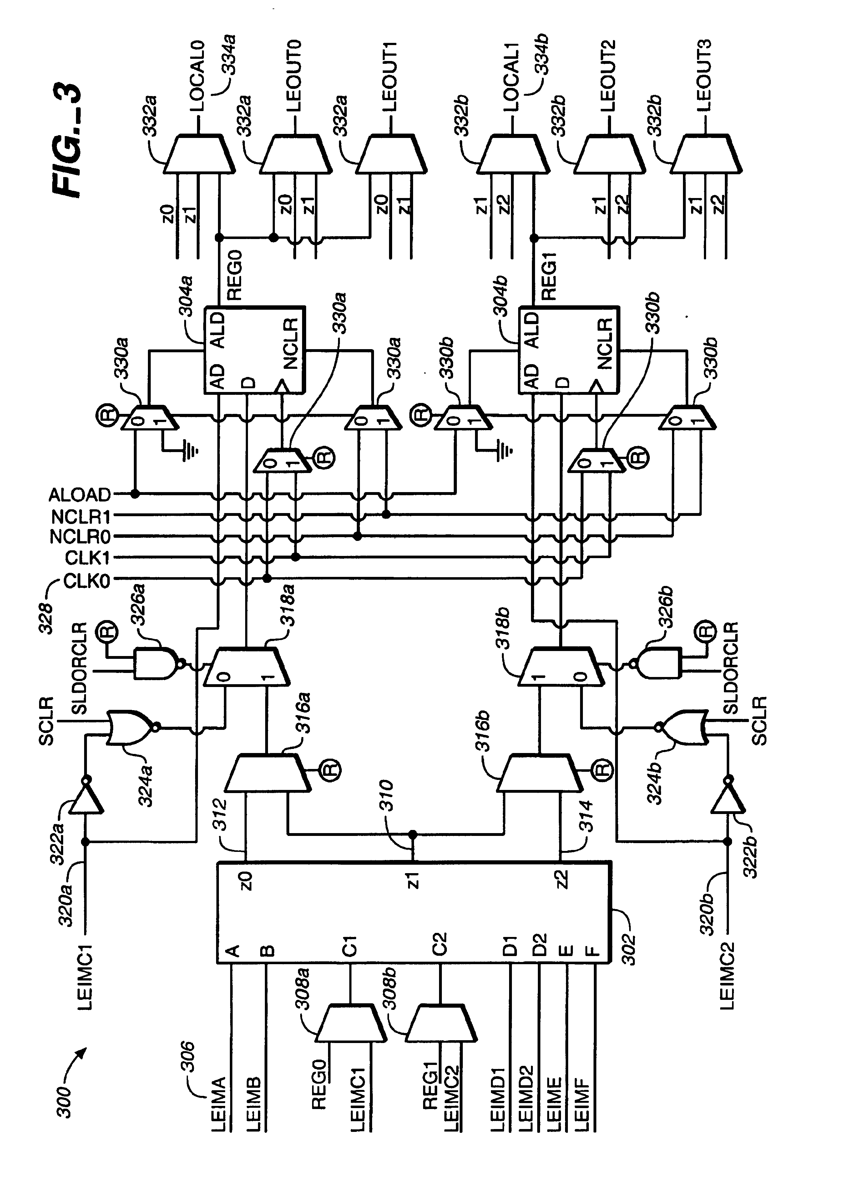
[0044]Similarly as in the previous embodiment 300, the LUT 402 provides a single output z1410 in a non-fractured mode and two outputs, z0412 and z2414, in a fractured mode. Also as in the previous embodiment the circuitry includes additional lines for LEMC1420a and LEMC2420b, multiplexers 416a, 416b, 418a, 418b, 430a, 430b, 432a, 432b, inverters 422a, NOR-gates 424a, 424b, NAND-gates 426a, 426b, stored values 428, and outputs 434a, 434b.

[0045]The embodiment of FIG. 4 advantageously exploits the additional input signals when the LUT 402 operates in the non-fractured mode. In this structure one of the extra inputs that resulted from splitting the original inputs (in this case C1) may be connected to its corresponding split input (in this case C2) at a corresponding multiplexer 408b. This allows the 6-LUT to bring the C signal on a single pin C1 and connect it to both C1 and C2 in the LUT 402. As a consequence, input pin C2 can now be used for another purpose, in this case to bring a ...


PUM


Abstract

A logic element includes memory elements, multiplexers, and controls. The multiplexers are arranged in levels including a highest level of multiplexers with inputs connected to the memory elements and outputs connected to inputs of a next-to-highest level of multiplexers and a first level of multiplexers with inputs connected to outputs of a second level of multiplexers and at least one output. The controls are connected to the multiplexers. In a first operational mode the controls determine a first-mode output at the at least one output of the first level of multiplexers, and in a second operational mode the controls determine a plurality of second-mode outputs at selected outputs of multiplexers not at the first level of multiplexers.

Description

BACKGROUND OF THE INVENTION[0001]The present invention relates to logic elements for use with programmable logic devices or other similar devices.[0002]Programmable logic devices (“PLDs”) (also sometimes referred to as CPLDs, PALs, PLAs, FPLAs, EPLDs, EEPLDs, LCAs, FPGAs, or by other names), are well-known integrated circuits that provide the advantages of fixed integrated circuits with the flexibility of custom integrated circuits. Such devices are well known in the art and typically provide an “off the shelf” device having at least a portion that can be electrically programmed to meet a user's specific needs. Application specific integrated circuits (“ASICs”) have traditionally been fixed integrated circuits, however, it is possible to provide an ASIC that has a portion or portions that are programmable; thus, it is possible for an integrated circuit device to have qualities of both an ASIC and a PLD. The term PLD as used herein will be considered broad enough to include such devi...

Claims


Application Information

Patent Timeline
IPC IPC(8): H03K19/177H03K19/173
CPCH03K19/17728H03K19/1737
Inventor LEWIS, DAVIDPEDERSEN, BRUCEKAPTANOGLU, SINANLEE, ANDY
Owner ALTERA CORP
Why Eureka
Try Eureka