
Location device

Active Publication Date: 2005-09-13
VALTRUS INNOVATIONS LTD +1
View PDF5 Cites 126 Cited by
  • Summary
  • Abstract
  • Description
  • Claims
  • Application Information

AI Technical Summary

Benefits of technology

[0011]According to this invention, a low cost location device is provided in a power socket which can transmit location information to a network appliance which is plugged into that socket.

Problems solved by technology

These techniques are however disadvantageous in providing location awareness for network appliances in that they each require a relative complex infrastructure to provide location signals.
The X10 protocol is disadvantageous in that an X10 control unit does not provide its address to a device connected to it, nor is the address necessarily correlated to the physical location.

Method used


Image

  • Location device
  • Location device
  • Location device

Examples


Embodiment Construction

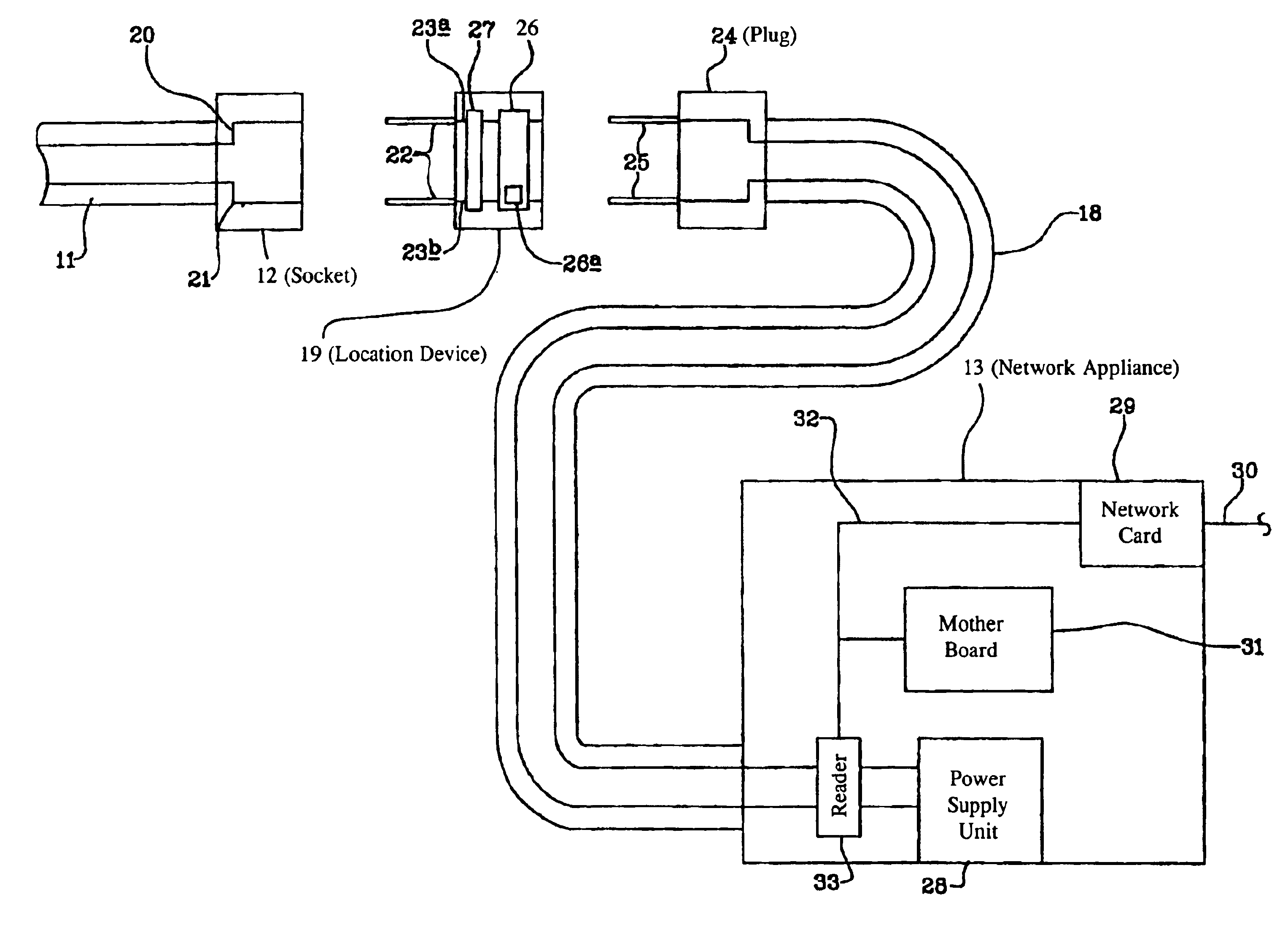
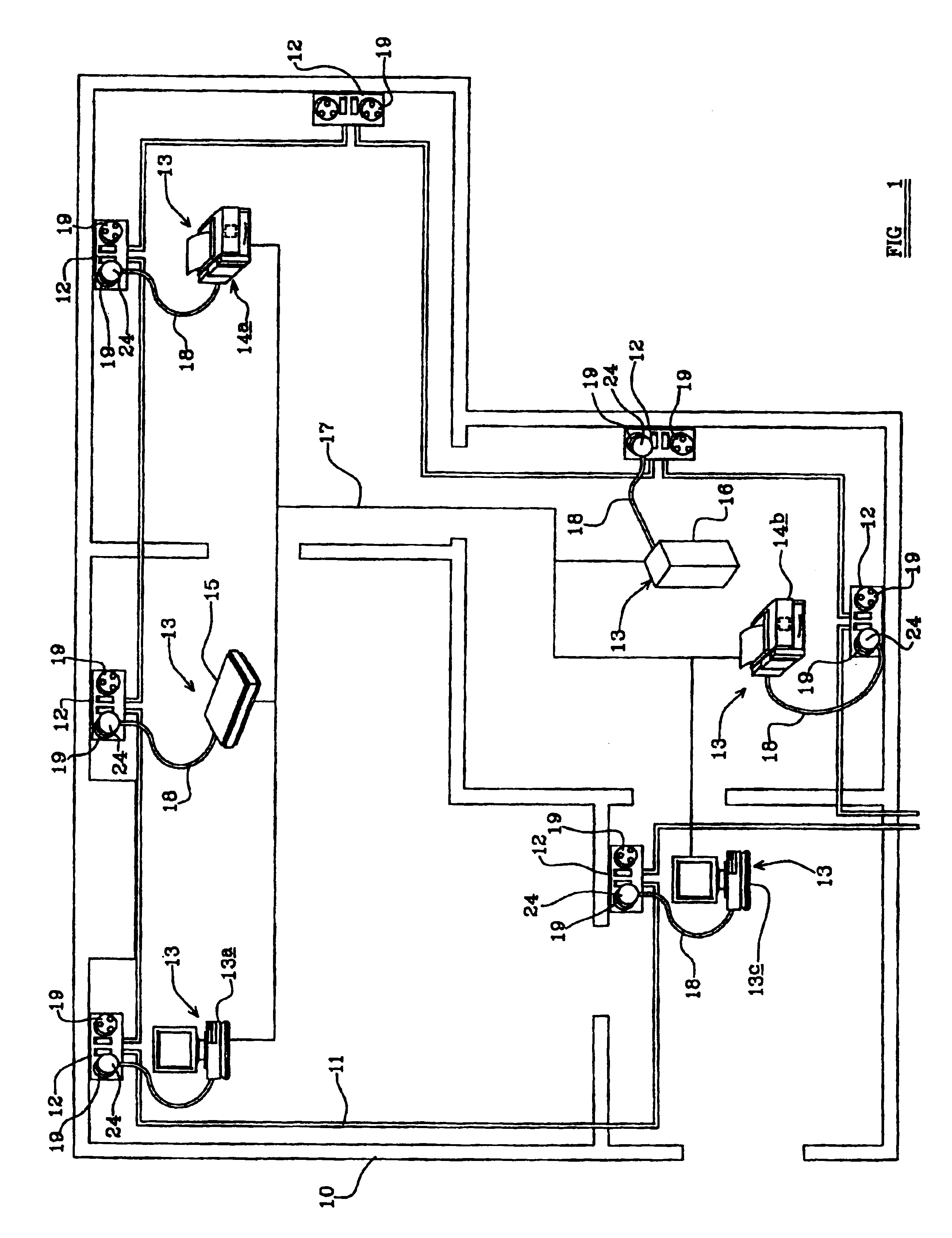
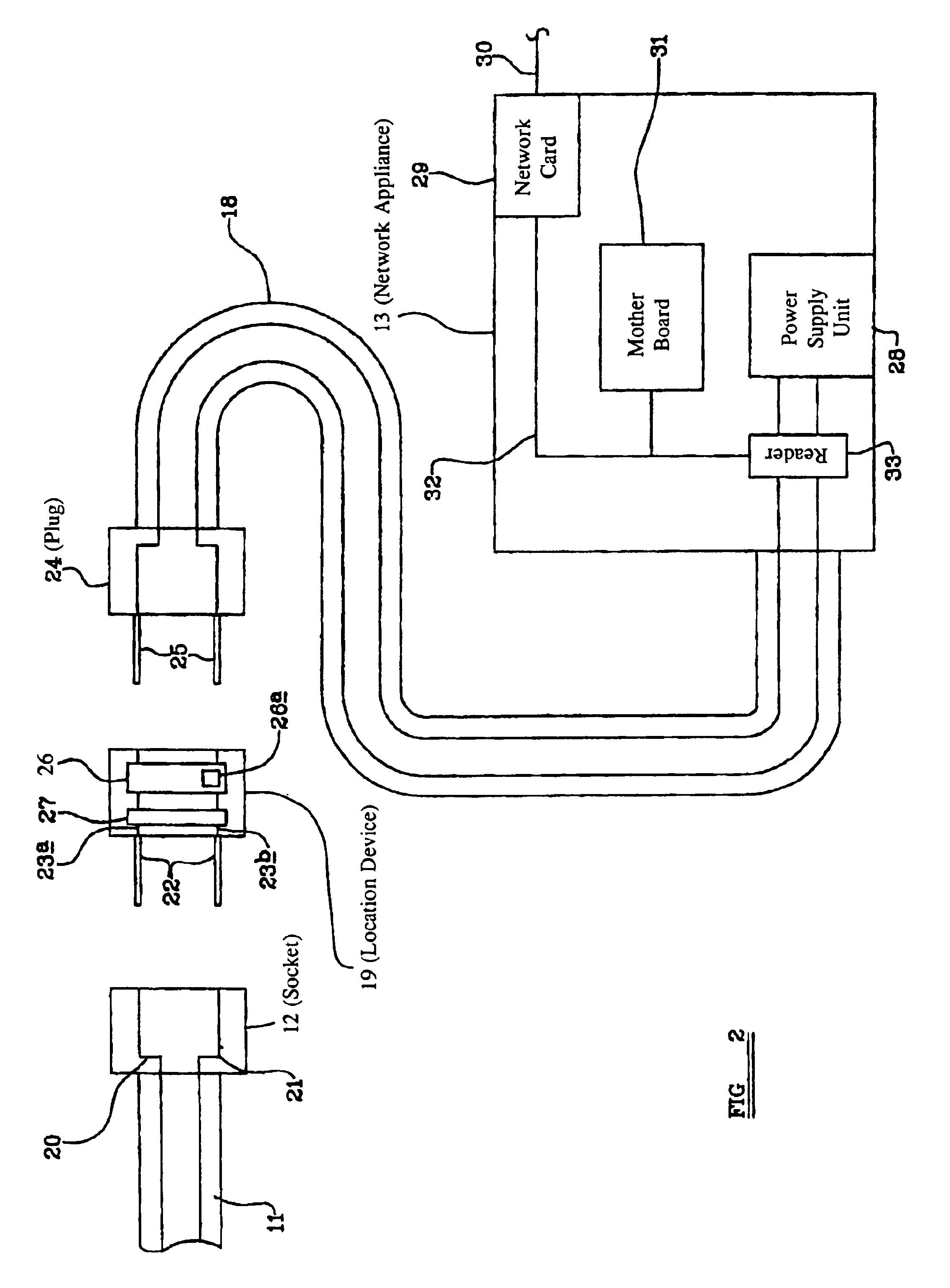
[0025]Referring now to FIG. 1, a plan of a building or part of a building is generally shown at 10. The building 10 is provided with a electrical mains power system comprising a mains power supply circuit 11 of conventional type which is provided with a plurality of mains power outlets comprising sockets 12 distributed throughout the building 10 in conventional manner. A plurality of network appliances 13 are located within the building, in the present example purely by way of illustration comprising personal computers 13a and 13b, printers 14a and 14b, a scanner 15 and a server 16. The network appliances 13 are interconnected by a suitable network 17. Each network appliance is connected in conventional manner by a power cable 18 to a mains socket 12 of the main power circuit 11.

[0026]The network 17 of FIG. 1 is purely a diagrammatic illustration, and may comprise an electrical connection such as Ethernet or FireWire, a radio network such as Bluetooth or 802.11 or any other appropri...


PUM


Abstract

A location device connectable to a power outlet of a mains power system, the location device being connectable to a power connection of a network appliance, the location device being operable to transmit location information to the network appliance via said power connection.

Description

FIELD OF THE INVENTION[0001]This invention relates to a location device, a network appliance and a network.BACKGROUND OF THE INVENTION[0002]In conventional computer networks where a plurality of appliances are connected via the network, each appliance has a network address which enables information to be routed to it over the network. The network address has no correlation with the physical location of the appliance.[0003]Providing network appliances with location awareness has many potential applications. These range from relatively simple applications such as inventory control so that for example an office manager would be able to identify the presence of each piece of equipment in an office or building, to more advanced applications such as providing information tailored to a user's physical location, such as the Hewlett Packard Cooltown project which aims to produce a connection between the physical and virtual worlds. A service location method for locating devices on a network ...

Claims


Application Information

Patent Timeline
IPC IPC(8): G08B1/00G08B1/08H04M11/04H04L12/28H04L29/08
CPCH04L12/2803H04L67/18H04L69/329H04L67/52
Inventor PERRET, STEPHANE
Owner VALTRUS INNOVATIONS LTD
Features
  • Generate Ideas
  • Intellectual Property
  • Life Sciences
  • Materials
  • Tech Scout
  • Unparalleled Data Quality
  • Higher Quality Content
  • 60% Fewer Hallucinations
Learn More