
Combined radar and laser detector having GPS receiver and using wireless communication

a combined radar and laser detector technology, applied in the field can solve the problems of large size of inability to easily receive various kinds of signals enabling the driver to drive safely, and difficulty in installing the combined radar and laser detector

Inactive Publication Date: 2005-09-13
CHANNEL TECH
View PDF12 Cites 25 Cited by
  • Summary
  • Abstract
  • Description
  • Claims
  • Application Information

AI Technical Summary

Benefits of technology

[0013]The information display module may further includes a serial communication unit for communicating with a user's computer, and a switching unit for temp

Problems solved by technology

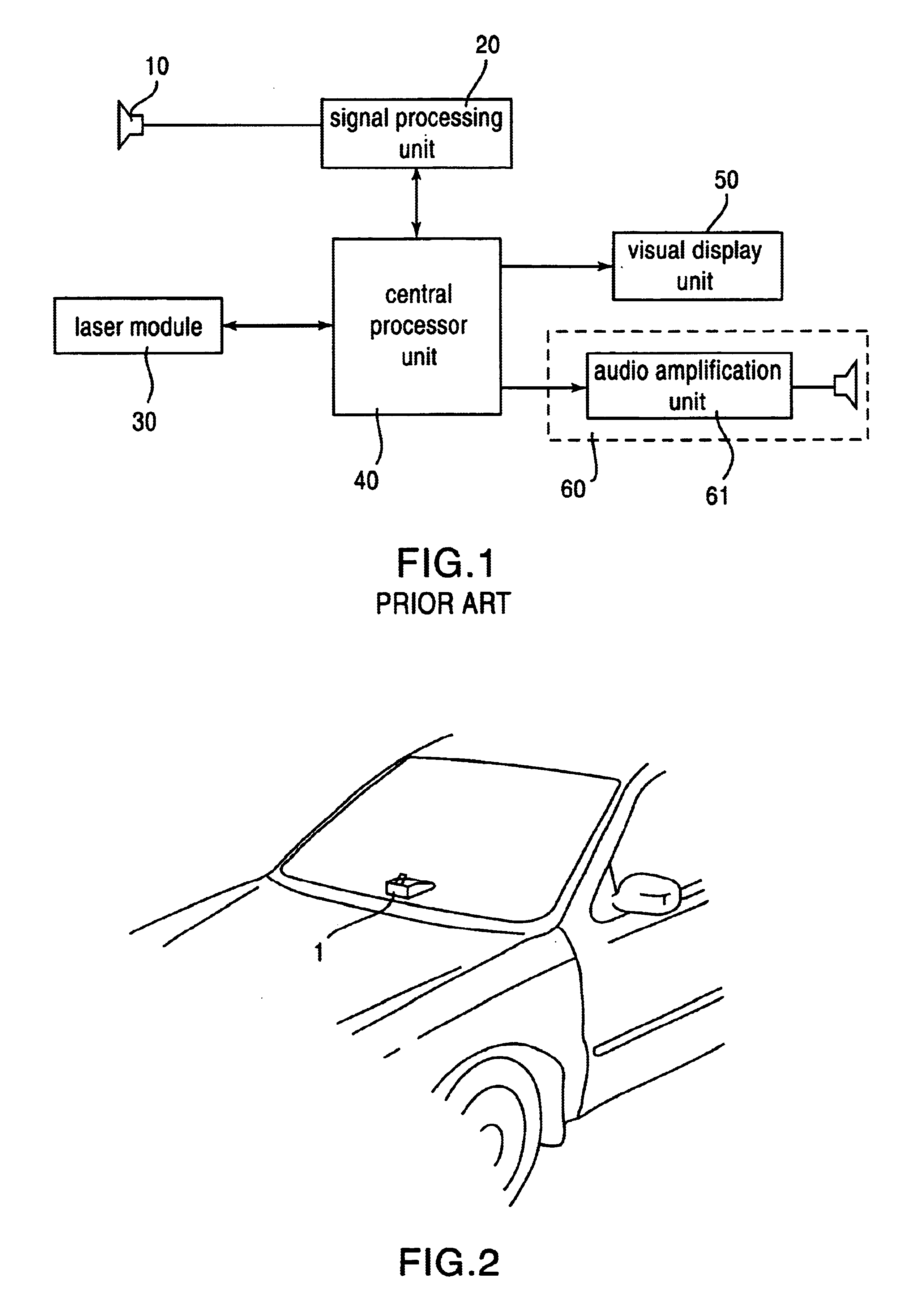
However, in the case of mounting the combined radar and laser detector 1 in a vehicle, a problem arises in that various kinds of signals enabling the driver to drive safely cannot be easily received.
However, in the case of mounting the horn antenna on the front of the vehicle, work is required to connect the horn antenna, placed outside the vehicle, with a visual display means and an audible indication means, placed inside the vehicle and adapted to provide traffic information to the driver through a wire, so that a problem arise in that it is difficult to install the combined radar and laser detector.
Additionally, the conventional combined radar and laser detector is constructed in such a way that the horn antenna and other components are integrated into a single body, so that the size of the combined radar and laser detector is large, and thus problems arise in that it is difficult to ensure a space for installation and excessive power consumption is incurred.
Furthermore, the conventional combined radar and laser detector is disadvantageous in that it cannot provide various kinds of information to the driver.
However, a problem still arises in that faulty operations occur due to frequency interference when the combined radar and laser detector is constructed to include the GPS receiver, so that it is difficult to guarantee the reliability of the operation of the combined radar and laser detector.

Method used


Image

  • Combined radar and laser detector having GPS receiver and using wireless communication
  • Combined radar and laser detector having GPS receiver and using wireless communication
  • Combined radar and laser detector having GPS receiver and using wireless communication

Examples


Embodiment Construction

[0022]Reference now should be made to the drawings, in which the same reference numerals are used throughout the different drawings to designate the same or similar components.

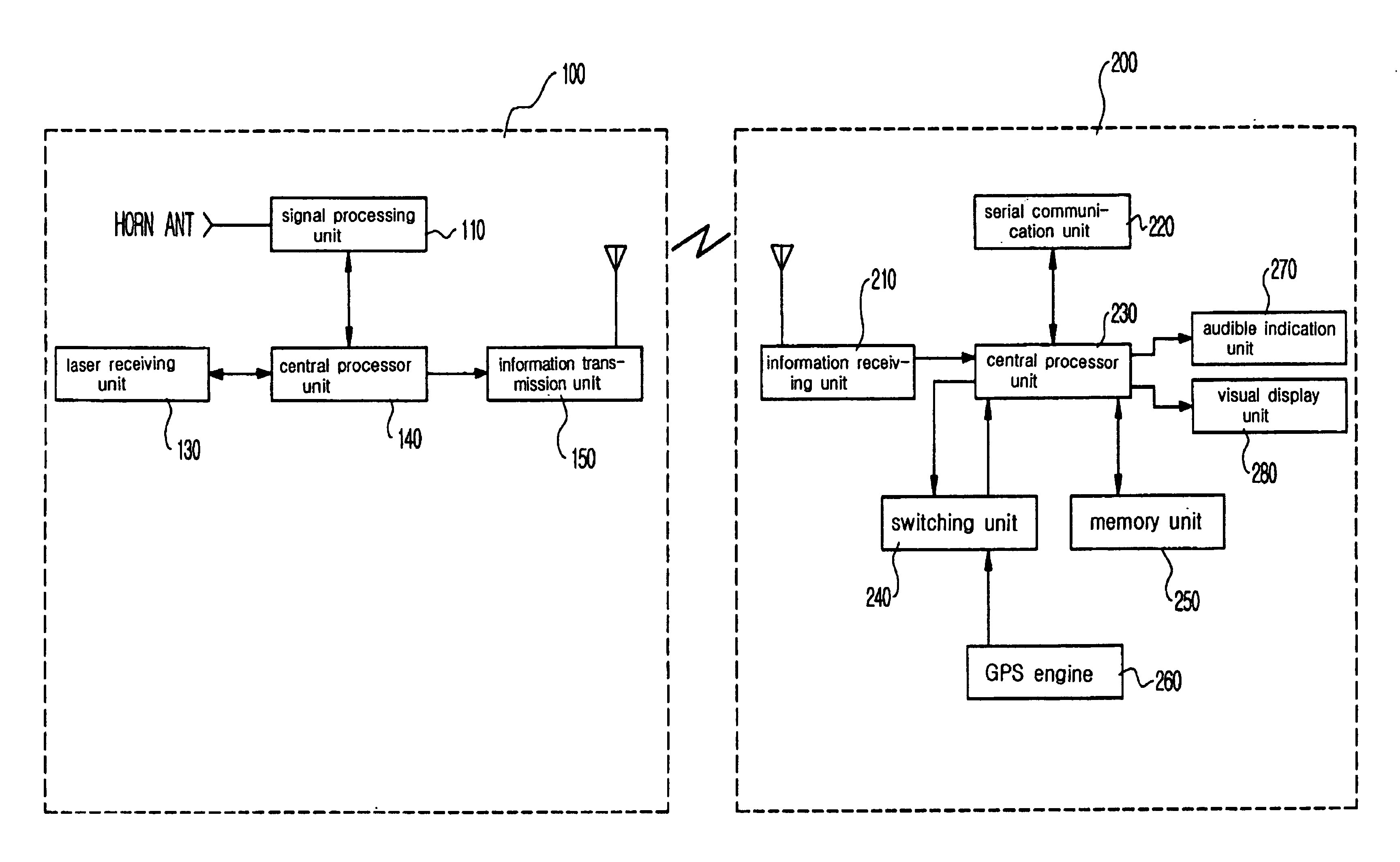
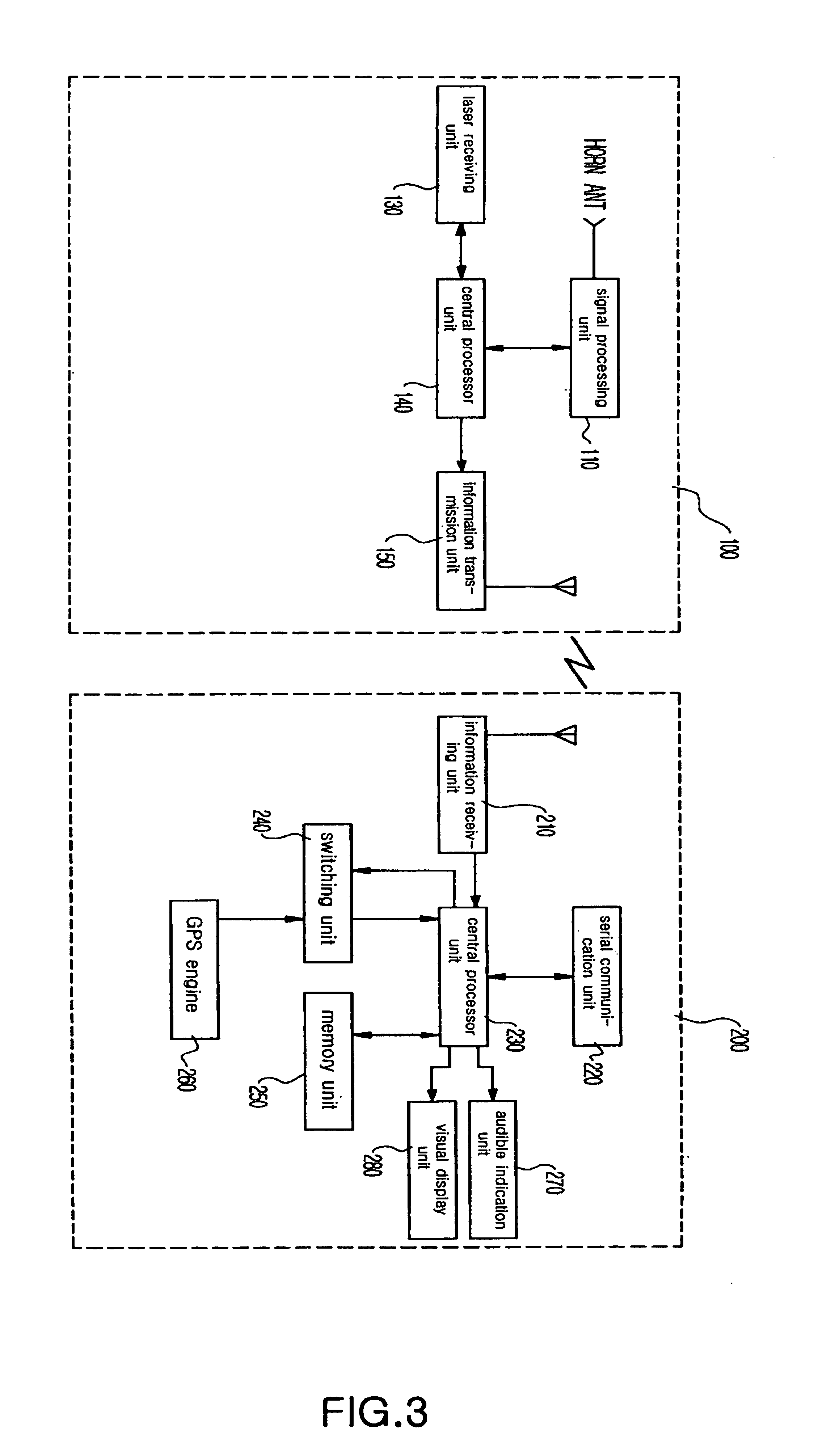
[0023]FIG. 3 is a block diagram schematically showing the construction of a combined radar and laser detector having a GPS receiver according to the present invention. The combined radar and laser detector of the present invention includes a signal receiving module 100 for detecting various kinds of signals that enable a driver to drive safely, and an information display module 200 for detecting GPS data related to the location and speed of a moving vehicle and informing the driver of the GPS data and the data detected through the signal receiving module 100. The signal receiving module 100 placed outside and on front of the vehicle and the information display module 200 placed inside the vehicle are constructed to wirelessly communicate with each other using an ultra high frequency of 300 to 400 MHz.

[0024]The...


PUM


Abstract

The present invention relates generally to a combined radar and laser detector that enables a driver to drive safely and, more particularly, to a combined radar and laser detector, in which a signal receiving module for receiving various kinds of signals including traffic information and an information display module for informing a driver of the signals are separated, the signal receiving module and information display module are constructed to communicate with each other using wireless communication, and the information display module is integrated with a Global Positioning System (GPS) receiver detecting GPS data related to the location and speed of a moving vehicle, so that the combined radar and laser detector can not only provide accurate traffic information to the driver, but also allow the installation thereof to be easy, the miniaturization thereof to be achieved, and power consumption to be minimized.

Description

BACKGROUND OF THE INVENTION[0001]1. Field of the Invention[0002]The present invention relates generally to a combined radar and laser detector that enables a driver to drive safely and, more particularly, to a combined radar and laser detector, which has a global positioning system receiver capable of detecting global positioning system data related to the location and speed of a moving vehicle and uses wireless communication, so that the combined radar and laser detector can not only provide accurate traffic information to a driver, but also allow the installation thereof to be easy, the miniaturization thereof to be achieved, and the power consumption thereof to be minimized.[0003]2. Description of the Related Art[0004]Various traffic safety devices for the safe driving of vehicles have been developed and used. In particular, the use of a combined radar and laser detector is generalized in U.S. and Europe to enable a driver to drive safely using traffic information, such as low sp...

Claims


Application Information

Patent Timeline
IPC IPC(8): G01S13/00G01S13/86G01S7/02G01S7/48G01S5/14G01S7/00G08G1/0962G01S19/14G01S19/42
CPCG01S7/022G01S7/4806G01S13/86G01S7/003G01S19/52G08G1/0962
Inventor KIM, DONG-RYEOLJUNG, SUN-WOUNG
Owner CHANNEL TECH
Learn More