Microscope for operation

a microscope and operation technology, applied in the field of microscopes for operation, can solve the problems of saline solution adhesion to the front lens, difficulty in fine operation, and difficulty for the operator to perform the operation, and achieve the effect of preventing glar

Inactive Publication Date: 2005-09-13
KK TOPCON
View PDF11 Cites 53 Cited by
  • Summary
  • Abstract
  • Description
  • Claims
  • Application Information

AI Technical Summary

Benefits of technology

[0035]According to the fifth aspect of the present invention, the reflected light on a back surface of the crystalline body is not entered into the observing optical system to prevent a glare from occurring.

Problems solved by technology

Accordingly, it is very difficult to perform a fine operation.
For example, when a focus distance F of the front lens 15 is too long, since a distance from the eyepiece of the microscope to the operated eye 8 is long, it is difficult for the operator to perform the operation.
When the operated eye 8 is, also, washed by physiological saline solution during an operation, there is a problem that the saline solution adheres to the front lens 15 by dispersion of the saline solution.
Furthermore, if the diameter of the front lens 15 is too large, a space between the operation instruments 11 is large by interference of the front lens.
In this case, there is an inconvenience that it is difficult to perform an operation with having the operation instruments 11 at both hands.

Method used


Image

  • Microscope for operation
  • Microscope for operation
  • Microscope for operation

Examples


embodiment 1

(Embodiment 1)

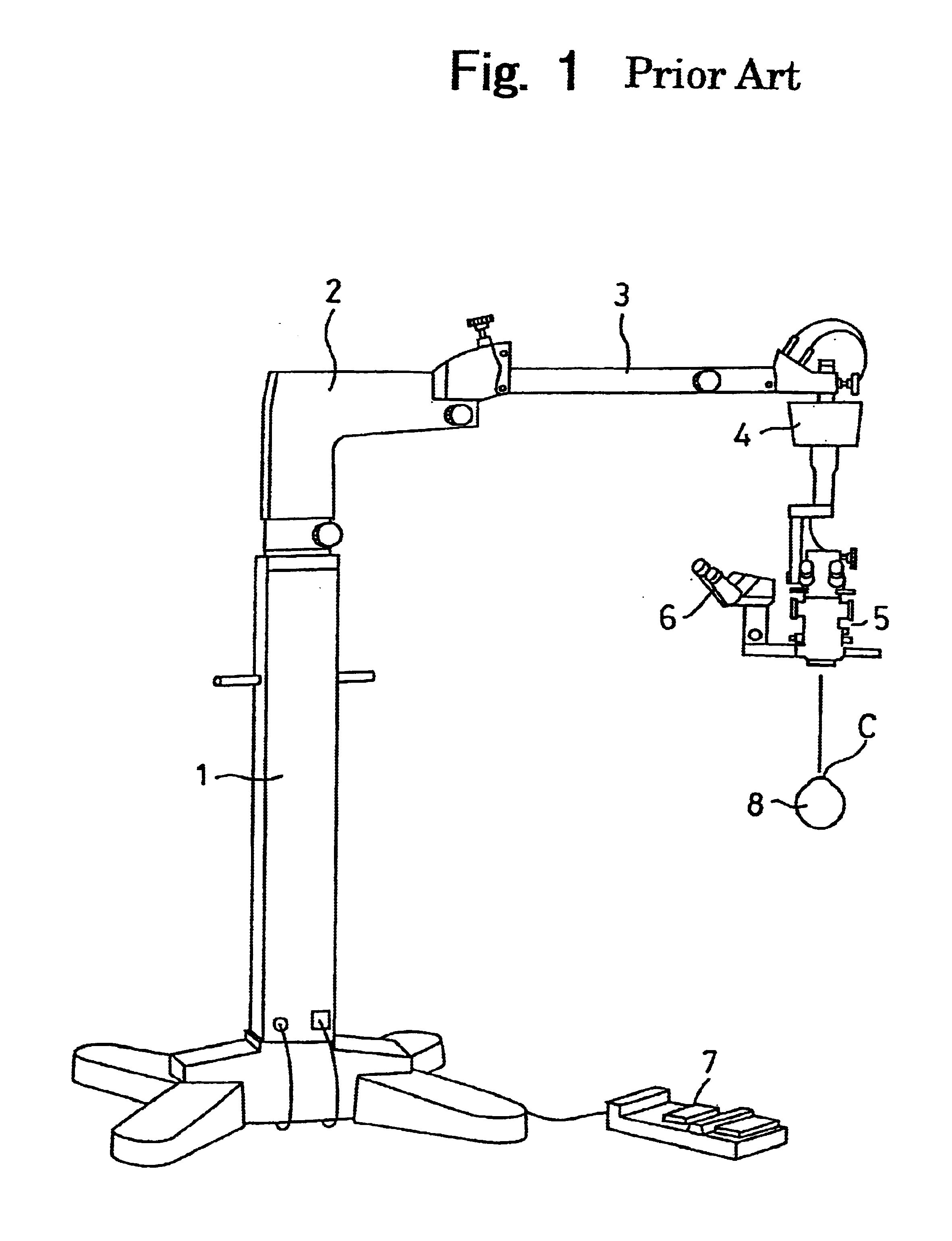
[0071]In FIG. 4, the same numerals are annexed to the identical elements with that of the prior art microscope described in FIG. 1.

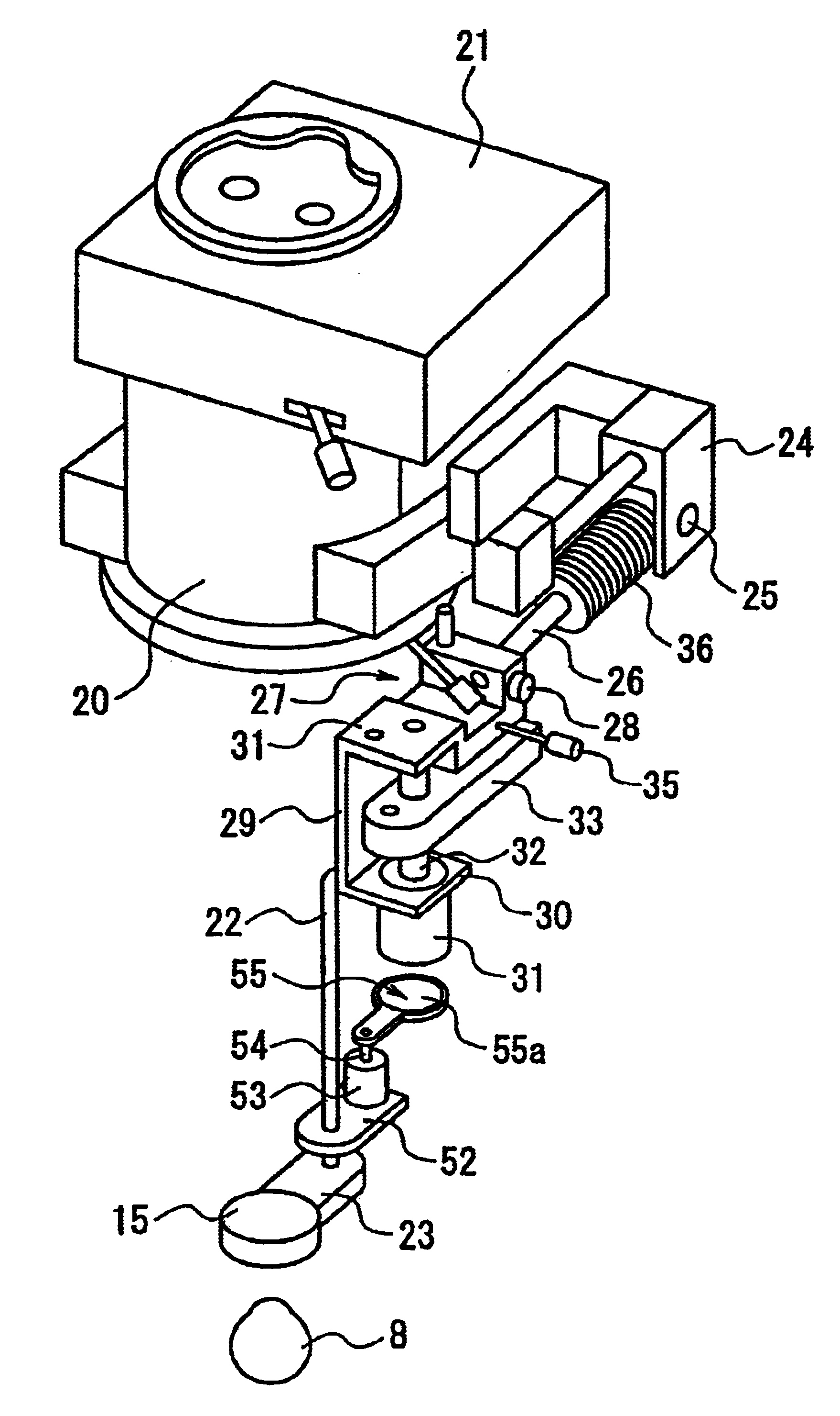
[0072]A microscope 5 for an operator comprises an objective body tube 20, an inverter portion 21 and a holding arm 22 as shown in FIG. 4.

[0073]FIG. 5 is a partially enlarged view of the objective body tube 20.

[0074]The objective body tube 20 is provided with an objective 14 as shown in FIG. 6. The inverter portion 21 is provided with a lens unit 21A for converting an inverted image whose up and down, right and left are visible inversely into an erect image, as shown in FIG. 7.

[0075]The lens unit 21A is reciprocated along slide rails 21B and is inserted into and moved out of an optical path of the objective 14 by a changing lever 21C.

[0076]A leading end of the holding arm 22 is provided with a holding plate 23 on which a front lens 15 is provided. The objective body tube 20 is provided with a fixed bracket 24 on which a turned rod 25 is moun...

embodiment 2

(Embodiment 2)

[0120]FIG. 15 shows a configuration in which the objective body tube 20 is micro-motioned upwardly and downwardly relative to an upward and downward micro-motion body portion 20A, and provided on the other end portion of the holding arm 22 of the front lens 15 is a rotating base 20B which is mounted rotatably on the body portion 20A.

[0121]The body portion 20A holds slidably a slide plate 20C as a slide member which can be moved upwardly and downwardly by a driving mechanism (not shown) which is provided in the body portion 20A. The objective body tube 20 is formed integrally with the slide plate 20C. Note that the front lens 15 is held by a holding frame 16A.

[0122]The aforementioned configuration has the following advantageous effects.

[0123]Pupils of incidence of an observing system and of ejection of an illuminating system in the microscope 5 for the operator are positioned adjacent to the objective 14. Images 20A′ and 20B′ of these pupils are focused on the neighborh...

embodiment 3

(Embodiment 3)

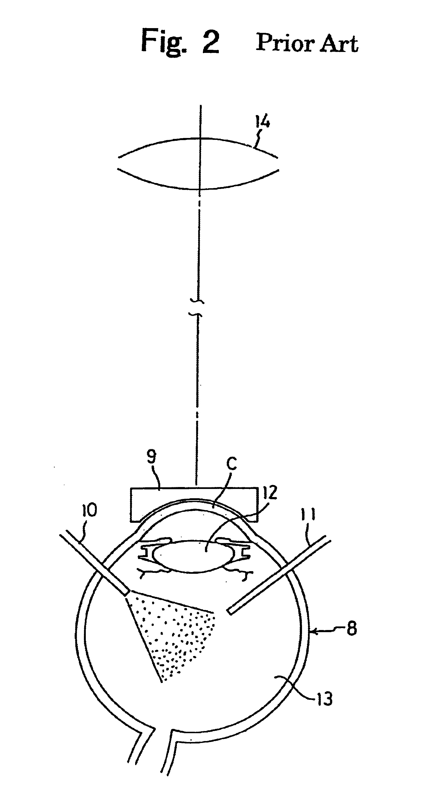
[0140]FIG. 18 is an explanatory view showing a positional relationship between the inserting part of the operation instrument 11 and front lens 15.

[0141]The operation instrument 11 is inserted into the operated eye 8 after the distance from the apex of the cornea C to the front lens 15 is determined to not occur the glare so that the operator can observe the image of the retina 8a of the fundus.

[0142]As shown in FIG. 19, because the inserting part 16 is positioned closely to the posterior focus surface of the front lens15, the conjugate point is generally infinity and the image by the objective 14 is not focused. On the other hand, since the anterior focus position u0 coincides with the position u1, the inserting part can not be observed when observing it through the objective 14.

[0143]Accordingly, the operator views one or more inserting parts 16 with the operator peeping from the sideward not through the front lens 15 by disengaging the eye with the eyepiece 39. Howe...


PUM


Abstract

Disclosed is a microscope for operation. This microscope for operation comprises a front lens 15 disposed between an eye 8 to be operated and an objective 14. The front lens collects an illuminating light P to guide the collected light within the eye for illuminating an interior of the eye. An operator performs an operation within the eye through an eyepiece 39. A refracting power of the front lens 15 is within a range of 30D to 50D.

Description

BACKGROUND OF THE INVENTION[0001]1. Field of the Invention[0002]The present invention relates to a microscope for operation in which an operation within an operated eye is performed by watching an eyepiece in a state of introducing collected illuminating light into the operated eye and illuminating within the operated eye with the collected illuminating light through a front lens which is disposed between the operated eye and an anterior focus position of an objective.[0003]2. Description of Prior Art[0004]Hitherto, there is known a microscope for operation, for example, a stereo microscope apparatus for operation having a configuration as shown in FIG. 1.[0005]In FIG. 1, numeral 1 denotes a pillar, numeral 2 a first arm, numeral 3 a second arm, numeral 4 a X-Y micro-motion device, numeral 5 an operation microscope (referred to, also, as a microscope device), numeral 6 an assistant microscope, numeral 7 a foot switch, and numeral 8 an eye or operated eye. Conventionally, when an ope...

Claims


Application Information

Patent Timeline
Patent Type & Authority Patents(United States)
IPC IPC(8): G02B21/00G02B21/06A61B19/00A61F9/007G02B21/24
CPCG02B21/0012G02B21/06A61B3/14
Inventor HORIGUCHI, MASAYUKIKITAJIMA, NOBUAKIKANAZAWA, NORIAKI
Owner KK TOPCON
Why Eureka
Try Eureka