Control system input apparatus and method

a control system and input device technology, applied in the direction of electrical apparatus casings/cabinets/drawers, pulse techniques, instruments, etc., can solve the problems of increasing the potential for short circuits and damage to components within the panel, mechanical switch panels are less than ideal for harsh environments, and the disadvantages of the foregoing types of control panels are inherent. to achieve the effect of easy finding a particular touch switch

Inactive Publication Date: 2005-09-13
TOUCHSENSOR TECH
View PDF26 Cites 63 Cited by
  • Summary
  • Abstract
  • Description
  • Claims
  • Application Information

AI Technical Summary

Benefits of technology

[0010]A control system input apparatus, or control panel, according to the present invention can take nearly any form. For example, it can have any number of convex or concave surfaces, or it can be a substantially planar panel having raised portions and/or depressions, i.e., a non-uniform cross-section or thickness, for enabling a user to more easily

Problems solved by technology

Certain disadvantages are inherent in the foregoing types of control panels.
For example, the apertures inherent to mechanical switch panels provide a path for fluids and contaminants to enter the rear portion of the control panel, increasing the potential for short circuits and damage to components within the panel.
Further, the mechanical switches themselves typically are assemblies of several individual parts which are subject to moisture or fluid intrusion.
As such, mechanical switch panels are less than ideal for use in harsh environments, unless peripheral protective enclosures are provi

Method used


Image

  • Control system input apparatus and method
  • Control system input apparatus and method
  • Control system input apparatus and method

Examples


Embodiment Construction

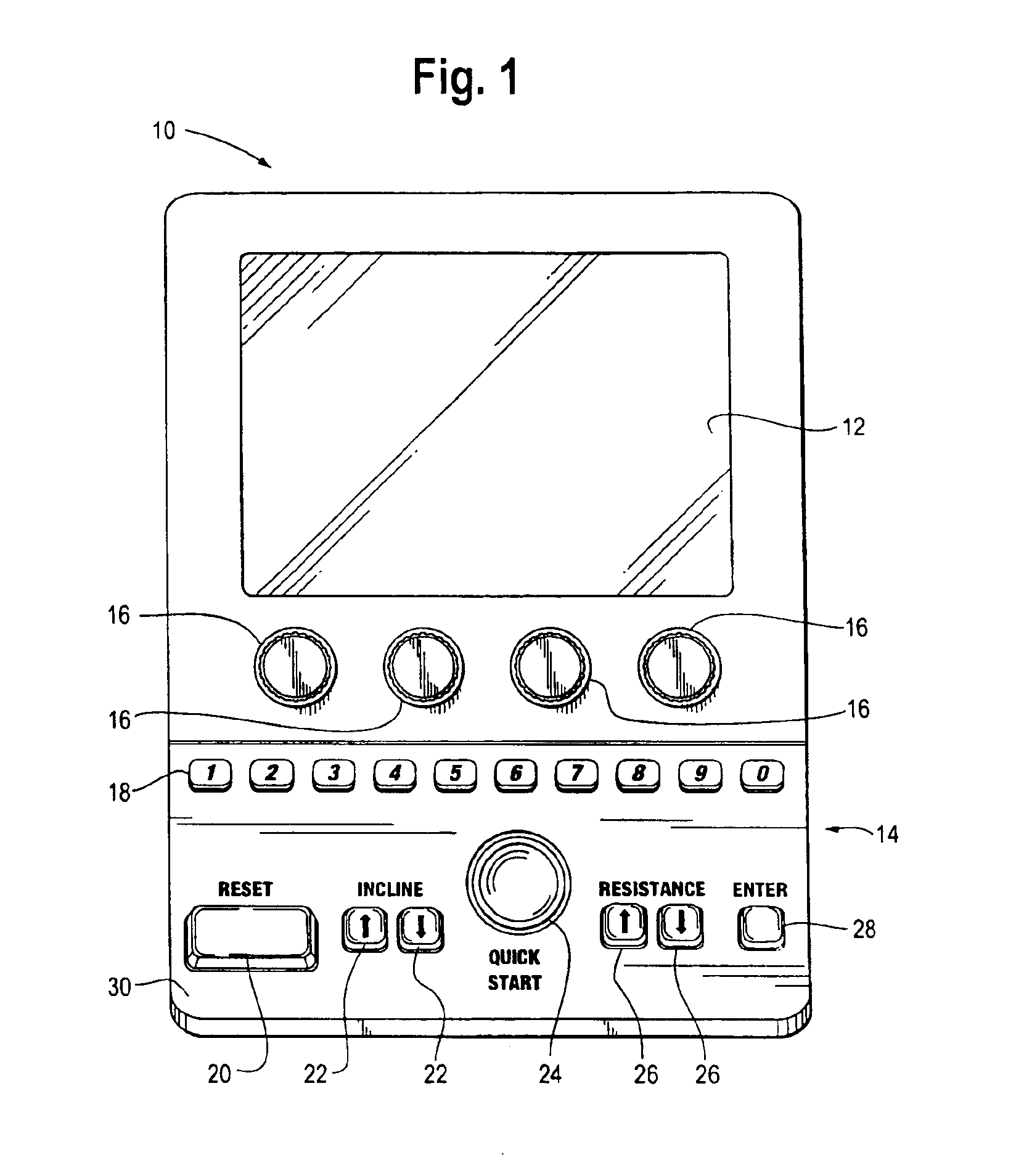
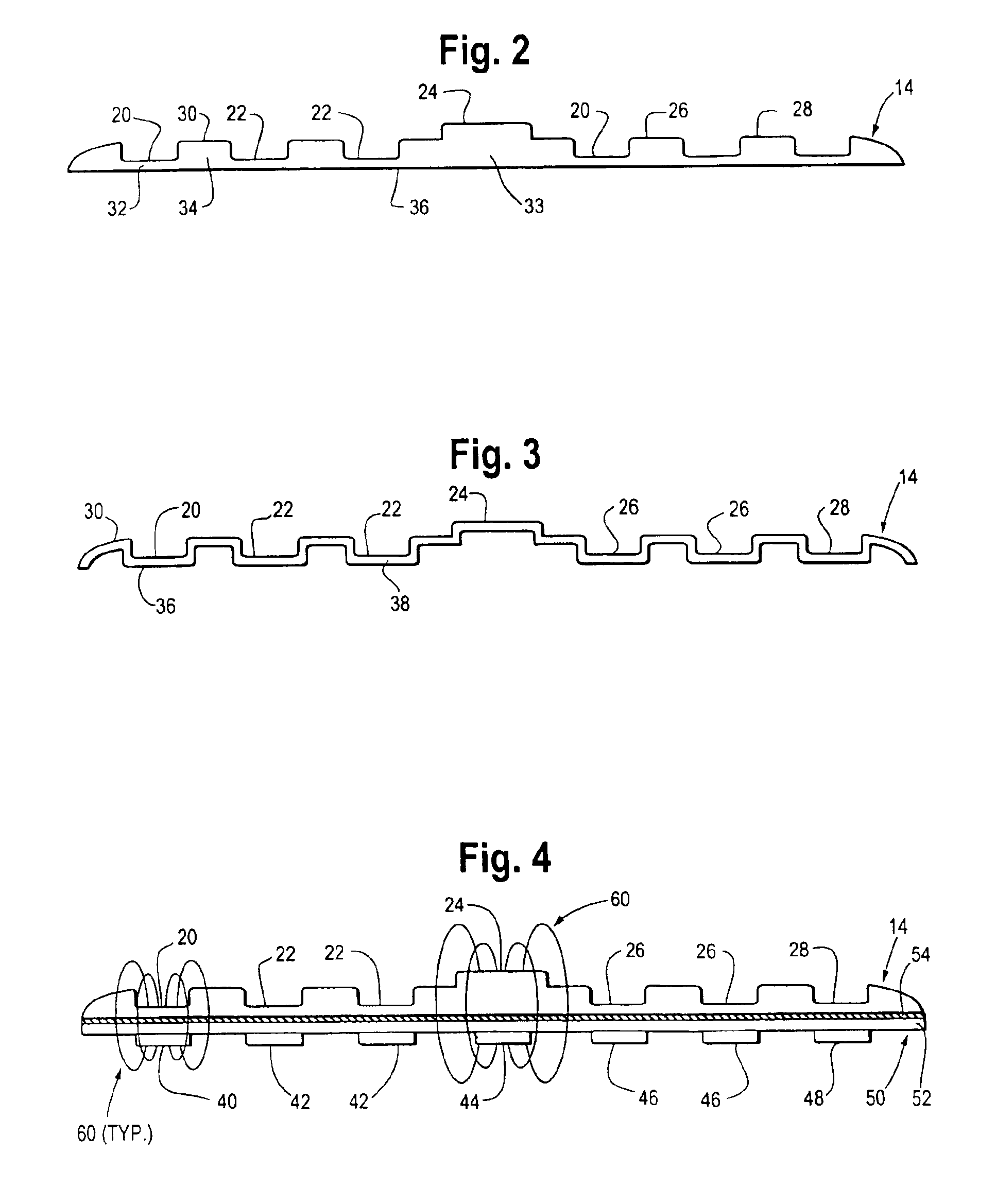
[0018]FIG. 1 illustrates a user interface 10 of a piece of exercise equipment, namely, a treadmill (not shown), embodying the present invention. User interface 10 includes a display 12 and a control panel 14. Control panel 14 is a substrate including a plurality of touch surfaces, such as display control touch surfaces 16 which control various functions of display 12, touch surfaces 18 for numerical input, touch surface 20 for resetting the treadmill's controls, touch surfaces 22 for adjusting the inclination of the treadmill's running surface, touch surface 24 for starting the treadmill, touch surfaces 26 for adjusting the treadmill's resistance, and touch surface 28 for indicating that data is to be entered to the treadmill's control system.

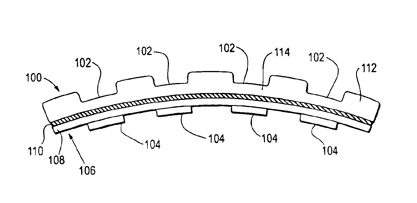
[0019]Control panel 14, as shown in FIG. 1, is generally planar. In other embodiments, control panel 14 can take any desired curved or angular shape. For example, control panel 14 can include convex, concave, and or angular elements.

[0020]The f...


PUM


Abstract

A control system interface integrates an electronic switching or sensing mechanism with an existing or custom-fabricated, functional or decorative equipment panel. The electronic switching or sensing mechanism is located on the rear surface of the equipment panel and a corresponding touch surface is defined on the front surface of the equipment panel. The electronic switching or sensing mechanism is responsive to a stimulus in the proximity of the touch surface, and it provides a control signal to a control system when it senses such a stimulus.

Description

CROSS-REFERENCE TO RELATED APPLICATIONS[0001]This application claims priority from U.S. Provisional Patent Application Ser. No. 60 / 289,225 filed on May 7, 2001.BACKGROUND OF THE INVENTION[0002]1. Technical Field[0003]The present invention relates generally to control system input apparatus and methods for making same. More particularly, the present invention relates to integration of electronic touch switches or sensors with shaped panels, such as decorative fascia and the like.[0004]2. The Prior Art[0005]Conventional electrical control panels typically comprise one or more mechanical or membrane switches installed on flat, or planar, panels having substantially uniform thickness and / or cross section. One known type of control panel includes one or more mechanical switches mounted on a flat panel having one or more apertures for accommodating the one or more mechanical switches. Such control panels are commonly used in connection with a wide variety of equipment, including industria...

Claims


Application Information

Patent Timeline
IPC IPC(8): H03K17/94H03K17/96G06F3/041
CPCH03K17/962A63B22/02A63B24/00
Inventor CALDWELL, DAVID W.
Owner TOUCHSENSOR TECH
Why Eureka
Try Eureka