Method for controlling the rotation of optical disk based on disk shapes

a technology of optical disk and rotational disk, which is applied in the direction of digital signal error detection/correction, instruments, recording signal processing, etc., can solve the problems of optical disk player breaking by vibration, data cannot be written and read stably, and the noncircular disk greatly vibrates and occurs loud noise, so as to prevent the vibration of the optical disk, write and read data stably and efficiently, and prevent the effect of loud nois

Inactive Publication Date: 2005-09-13
SHINANO KENSHI
View PDF17 Cites 4 Cited by
  • Summary
  • Abstract
  • Description
  • Claims
  • Application Information

AI Technical Summary

Benefits of technology

[0024]In the present invention, proper rotational speed of the optical disk can be defined on the basis of the shape of the optical disk. Data can be written and read stably and efficiently without reference to the shape of the optical disk. Vibration of the optical disk can be prevented, so the optical disk player is not damaged. Further, loud noise can be prevented. If the signals included in the reflected beam is analyzed when the optical disk is attached, the shape of the optical disk can be recognized when the optical disk is attached to the optical disk player, so that the optical disk can be always rotated at the proper rotational speed.

Problems solved by technology

As the result of the collision, a lifting force works to the noncircular disk, so that the noncircular disk greatly vibrates and occurs loud noise.
Further, data cannot be written and read stably.
In the worst case, the optical disk player is broken by the vibration.
If the rotational speed of the optical disk player is fixed at lower speed so as to stably use a noncircular disk, it takes a long time to write data in and read data from a circular disk too.

Method used


Image

  • Method for controlling the rotation of optical disk based on disk shapes
  • Method for controlling the rotation of optical disk based on disk shapes
  • Method for controlling the rotation of optical disk based on disk shapes

Examples


Embodiment Construction

[0032]Preferred embodiments of the present invention will now be described in detail with reference to the accompanying drawings. In the present embodiment, the optical disk player is capable of using a circular disk, whose diameter is 8 cm or 12 cm, and a noncircular disk, which is formed into a rectangular shape and whose length is 8 cm.

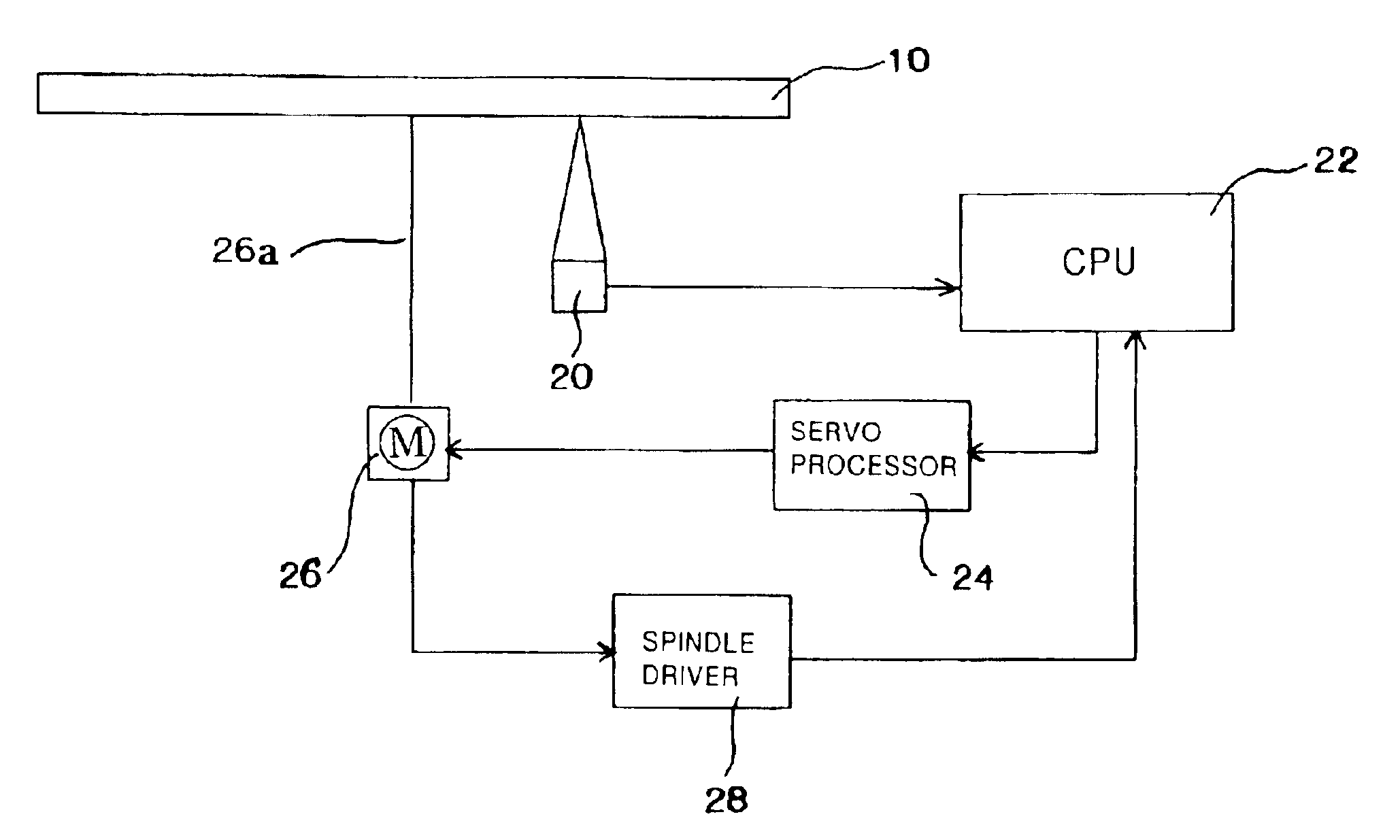
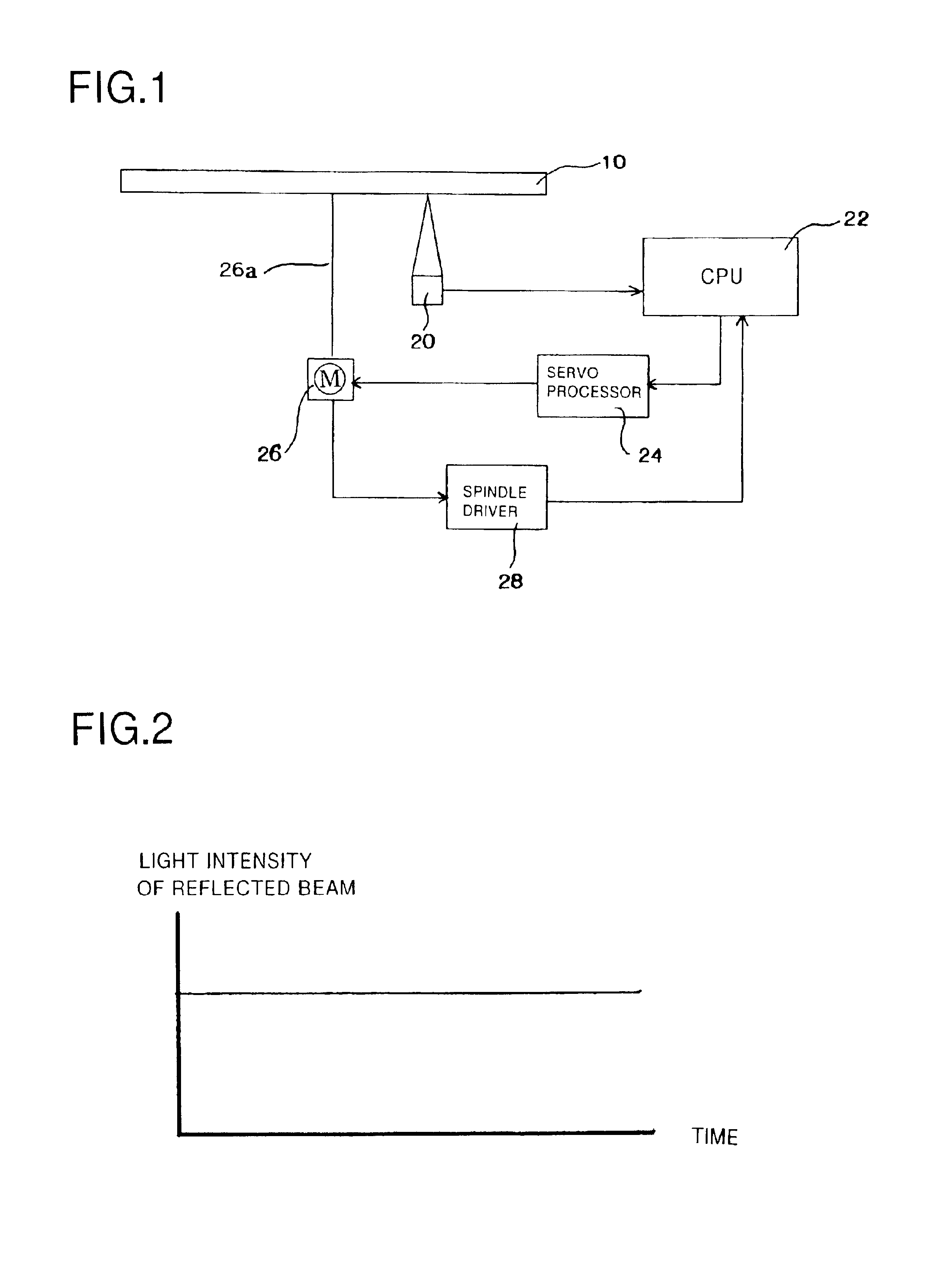
[0033]Firstly, a structure of the optical disk player of the present embodiment will be explained with reference to FIG. 1.

[0034]FIG. 1 is a block diagram of the optical disk player. A symbol 10 stands for an optical disk. An optical pickup 20 irradiates a laser beam to the optical disk 10 rotating and receives a reflected beam reflected from the optical disk 10. A CPU 22 analyzes signals included in the reflected beam received by the optical pickup 20, so as to recognize a type or a shape of the optical disk. Namely, the CPU 22 acts as the analyzing means. A servo processor 24 controls rotational speed of the optical disk 10 on the basis of the ty...


PUM

PropertyMeasurementUnit
diameteraaaaaaaaaa
lengthaaaaaaaaaa
diameteraaaaaaaaaa

Abstract

The optical disk player of the present invention is capable of controlling rotational speed of an optical disk, on the basis of a shape of the optical disk, so as to stably and efficiently write data in and read data from the optical disk. The optical disk player comprises: a motor for rotating the optical disk; and an optical pickup for irradiating a laser beam to the optical disk and receiving a reflected beam reflected therefrom. A CPU analyzes signals included in the reflected beam so as to recognize a shape of the optical disk. A servo processor controls rotational speed of the optical disk on the basis of the shape of the optical disk recognized by the CPU.

Description

BACKGROUND OF THE INVENTION[0001]The present invention relates to an optical disk player and a method of controlling an optical disk player, more precisely relates to an optical disk player and a method of controlling an optical disk player, in each of which rotational speed of an optical disk, e.g., CD-R / RW, DVD-R / RW, can be properly changed on the basis of a shape of the optical disk.[0002]Many types of optical disk players, in each of which a circular optical disk or disks are attached, are known (see Japanese Patent Gazette No. 11-66712, etc.). Recently, noncircular optical disks (see FIGS. 5 and 6) are used.[0003]The noncircular optical disk 30 shown in FIG. 5 is made by merely cutting a circular optical disk. Data can be written in a whole face 30a of the disk 30. But, a part 30b is actually used as an effective recording part because data can be continuously written in and read from the part 30b. [0004]The noncircular disk 40 shown in FIG. 6 is made by covering one side face ...

Claims


Application Information

Patent Timeline
Patent Type & Authority Patents(United States)
IPC IPC(8): G11B19/26G11B19/12G11B7/0037G11B7/0033G11B7/00G11B7/004G11B7/085G11B19/20G11B19/28
CPCG11B7/0033G11B7/0037G11B19/12G11B19/26
Inventor HARATA, TSUYOSHI
Owner SHINANO KENSHI
Why Eureka
Try Eureka