Method for communication traffic load balancing between cells of a communication system

a communication system and traffic load technology, applied in the direction of transmission, transmission monitoring, electrical equipment, etc., can solve the problems of not being able to acquire or install, needing to allocate new bandwidth, and increasing the number of cells, so as to prevent the rapid variation of the cell size, and reduce the cost of installation.

Inactive Publication Date: 2005-09-13
LUCENT TECH INC
View PDF7 Cites 9 Cited by
  • Summary
  • Abstract
  • Description
  • Claims
  • Application Information

AI Technical Summary

Benefits of technology

[0012]One major advantage of the invention is that the current traffic load penalty factors are determined depending on those which have been calculated previously in the defined loop. This provides the positive effect that handovers are achieved in a more controlled way, i.e. the proposed method leads to a smoother change of the cell borders in contrast to other algorithms which often overreact. This way, a too rapid variation of the cell size can be prevented.
[0013]A further advantage of the invention is that the mapping function preferably maps the free traffic resources into an evaluation factor. This is done particularly in terms of free traffic channels, whereby the mapping function is supposed to be a discrete and monotonic decreasing function. Thus a small number of free channels correspond to a high evaluation factor.
[0014]A possible solution to determine the evaluation factor is to classify the current number of free channels Nch into one of n bands, whereby each band specifies a predefined evaluation factor Ci. The bands are defined by a set of load thresholds L1 . . . Ln−1 representing the maximum number of free traffic channels for the corresponding band. The load thresholds and the evaluation factors must fulfill the following conditions:
[0015]Most advantageously, the invention provides a defined assignment which allows a simple way to determine the above described bands of free traffic channels and the corresponding evaluation factors automatically. Thus, the inventors show that the following terms are able to express the inventive concept: Li=[(1-Sload / 100)·in-i]·Nch, ⁢with⁢ ⁢1≤i≤n-1,⁢Ci=[(Cmax-0.1)·(n-in-1)a+0.1], ⁢with⁢ ⁢1≤i≤n-1,
[0016]VariableMeaningLiload threshold, i. e. maximum number of free trafficchannels for the corresponding band iIband indexNnumber of bandsSloadpercentage of traffic load at which the load balancingshould startNchthe total number of traffic channelsCievaluation factor for band iCmaxmaximum evaluation factionAparameter which determines the rise of the evaluationfactor
[0017]Even more advantageously the inventive current traffic load penalty factors can be determined by the following recurrence formula:

Problems solved by technology

Yet, additional channels need to allocate new bandwidth which is not available for most of the operators.
Moreover, additional cells require new locations, which are either not possible to acquire or are very expensive to install.
Both methods do not exploit the unused capacity in lightly loaded cells.
However, the latter method is even more cost effective than installing additional base stations for additional cells.
However, additional channels are quite expensive and the method implies a heavy control function.
On the one hand, the highly loaded cells operate at a high blocking probability, which corresponds to the local capacity limit.
On the other hand, the low loaded neighboring cells have some unused capacity, which conventionally can not be exploited to absorb traffic of the highly loaded cells.
Yet, these methods usually use only the current load situation for deciding whether or not a call is to be directed to a neighbor cell.
This effect leads to rapid variations of the cell boundary.
Thus, it becomes probable that a lot of unnecessary or ping-pong handovers occur, increasing the signaling load on the base station controllers.
As there is always a certain probability for handover failures, the overall network performance will be degraded due to the increased number of handovers.

Method used


Image

  • Method for communication traffic load balancing between cells of a communication system
  • Method for communication traffic load balancing between cells of a communication system
  • Method for communication traffic load balancing between cells of a communication system

Examples


Embodiment Construction

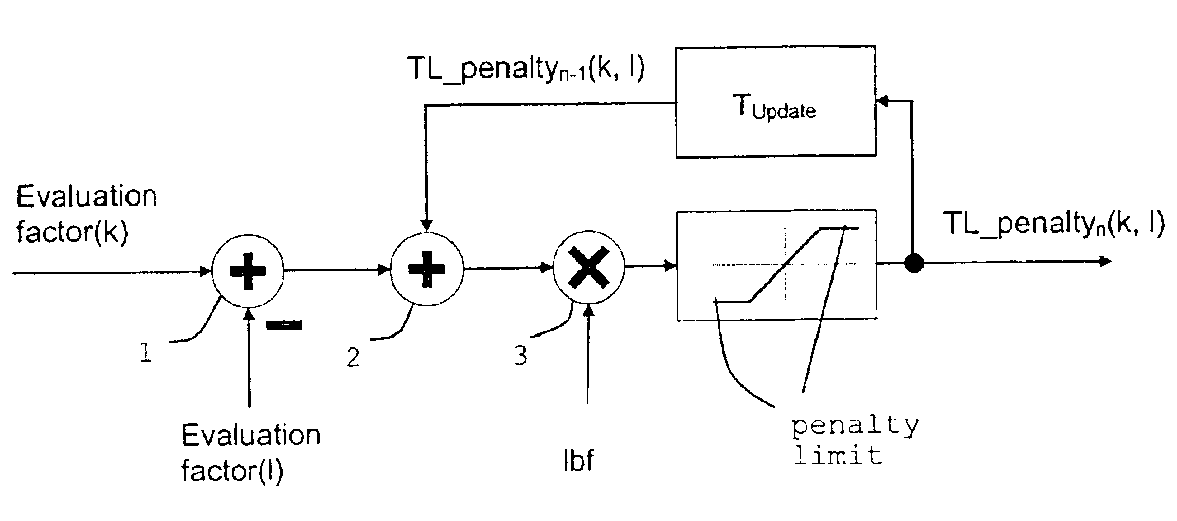
[0024]According to the invention, first a universal mapping function fMap(Nfree) is introduced to map the traffic load into an evaluation factor or correction factor for the modified power budget handover. While the traffic load is measured in terms of the number of free traffic channels Nfree, the evaluation or correction factor C applied to the power budget calculation for the handover threshold comparison and target cell ranking, which, will be explained in more detail below, is defined in units of dB. Thus the mapping functionality is given by

C=fMap(Nfree).

[0025]The mapping function is discrete and has to be a monotonic decreasing function. Moreover, if no traffic channel is free, Nfree=0, a maximum correction factor C=Cmax has to be assigned. Otherwise, if all available traffic channels are free Nfree=Nch, the correction factor has to be set to Cn, Cn=0 for simplicity. The term Nch denotes the total number of channels in the cell.

[0026]A possible solution to determine the corre...


PUM


Abstract

A method is proposed for communication traffic load balancing between cells of a communication system which are differently loaded. An evaluation factor is determined by a predefined mapping function for each of a home cell k and at least one other cell l, each evaluation factor being a measure of the load on the respective cells. At least one comparing factor is determined with respect to the home cell evaluation factor by comparing the evaluation factor of the home cell with those of the at least one further cells. Each of the comparing factors has a corresponding traffic load penalty factor. The traffic load penalty factors are a measure of load difference and/or transmission quality between the cells. This assignment is repeated in a loop such that current traffic load penalty factors are determined depending on predefined traffic load penalty factors and/or forerunner traffic load penalty factors determined in earlier cycles of the loop. The current traffic load penalty factors are used to evaluate unused transmission capacity of a cell and/or cells in comparison to the home cell and/or a time at which at least a part of the traffic of the home cell is handed over to at least one cell with unused capacity.

Description

CROSS REFERENCE TO RELATED APPLICATION[0001]This application claims priority of European Application No. 02251015.0 filed on Feb. 14, 2002.FIELD OF THE INVENTION[0002]The invention relates to balancing traffic load between cells of a communication system.BACKGROUND OF INVENTION[0003]Methods and apparatus are known in the art which are used to cope with the problem of limited resources on the one hand and the increased number of mobile subscribers on the other. To overcome this problem different solutions are imaginable. These can be roughly classified in hardware solutions, improved channel allocation schemes and the change of handover boundary parameters.[0004]Of course digital hardware i.e. resources and channels or cells, respectively can be installed at locations where the network is expected to become overloaded. Yet, additional channels need to allocate new bandwidth which is not available for most of the operators. Moreover, additional cells require new locations, which are e...

Claims


Application Information

Patent Timeline
Patent Type & Authority Patents(United States)
IPC IPC(8): H04W16/06
CPCH04W16/06
Inventor GUNREBEN, PETER CHRISTIANJUGL, ENRICOPAMPEL, HOLGER
Owner LUCENT TECH INC
Why Eureka
Try Eureka