Device for sealing a lubricant reservoir and method for lubricating the internal cavity of a tire

Inactive Publication Date: 2005-09-20
MICHELIN RECH & TECH SA
View PDF29 Cites 8 Cited by
  • Summary
  • Abstract
  • Description
  • Claims
  • Application Information

AI Technical Summary

Benefits of technology

[0026]According to another aspect of the invention a safety support is also provided for a mounted assembly comprising a wheel rim and a tire defining a cavity, said assembly being capable either of a rolling condition with the tire inflated, where the pressure inside the cavity is at least sufficient to avoid other than momentary contact between the inside of the tire tread and the safety support, or of a condition of rolling flat, where the pressure inside the cavity is such that the inside of the tire tread comes into substantially prolonged contact with the safety support, said support being able to accommodate a rese

Problems solved by technology

This avoids direct contact between the tire and the wheel rim, which generally results in rapid deterioration of the tire.
Such a device has certain functional limitations.
For example, it sometimes occurs that the temperature of a tire increases even at normal pressure, up to levels that can cause the plug to melt.
The lubricant is then ejected out of the reservoir and this can give rise to various types of problems, for example problems of non

Method used


Image

  • Device for sealing a lubricant reservoir and method for lubricating the internal cavity of a tire
  • Device for sealing a lubricant reservoir and method for lubricating the internal cavity of a tire
  • Device for sealing a lubricant reservoir and method for lubricating the internal cavity of a tire

Examples


Example

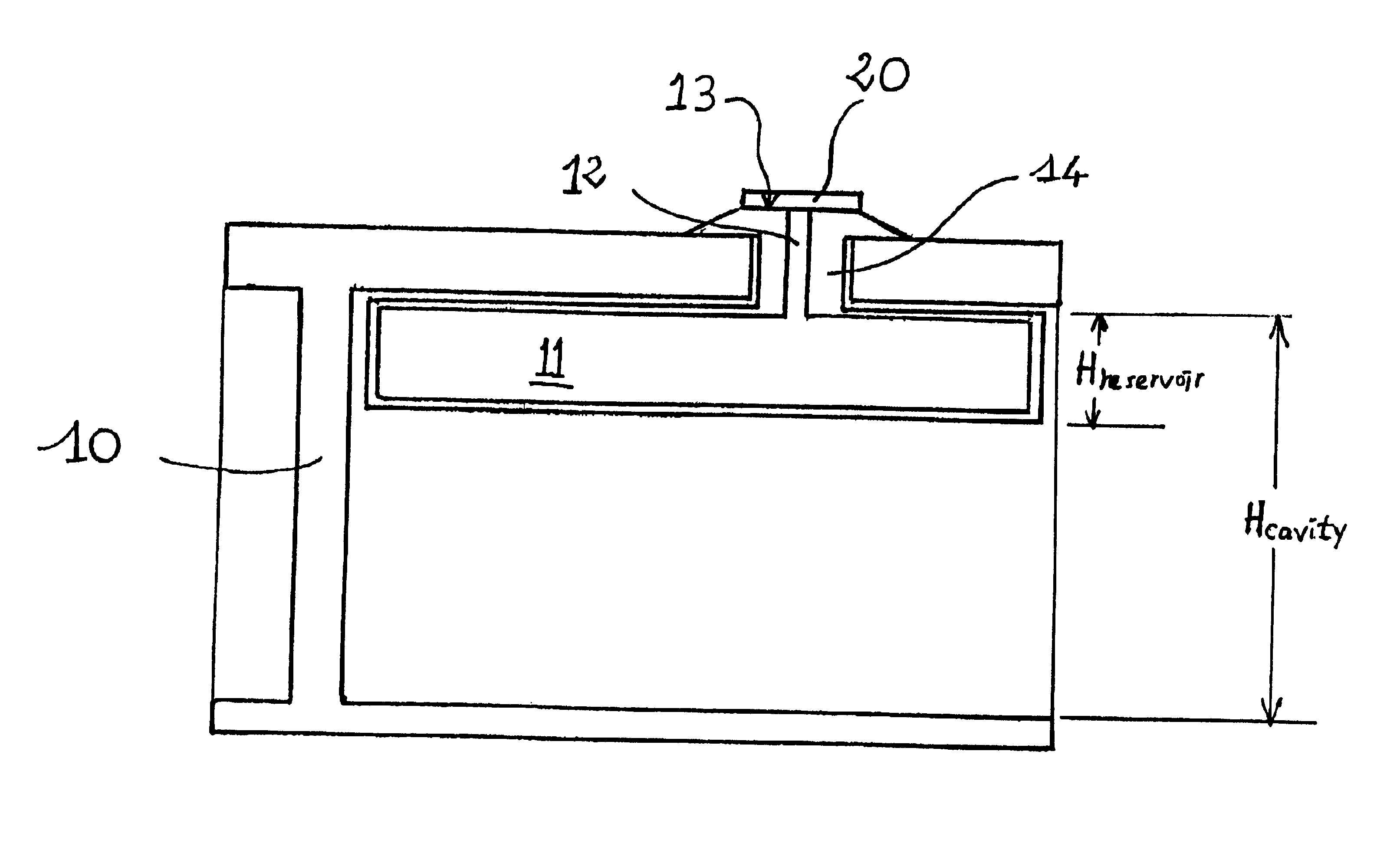
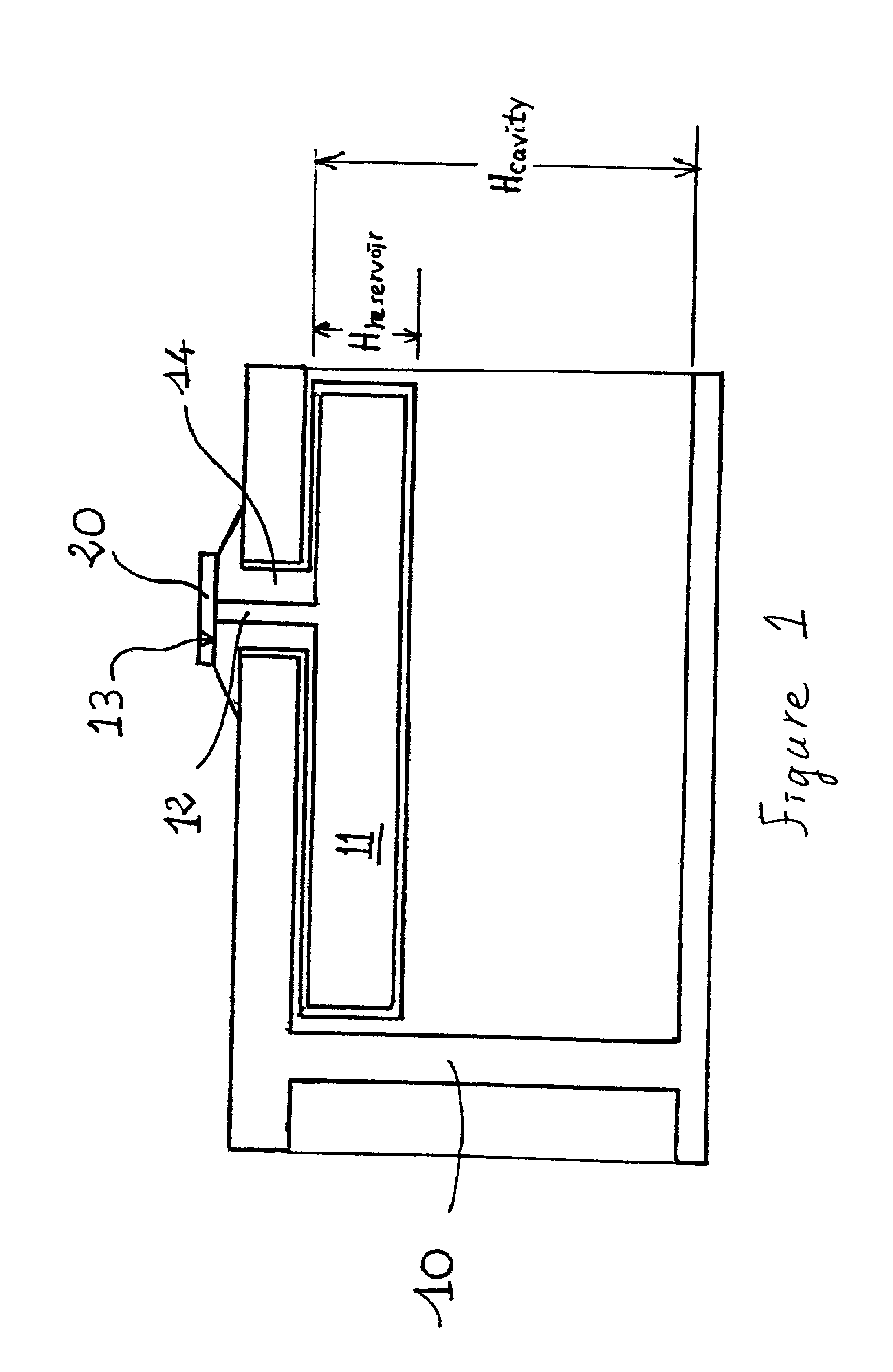
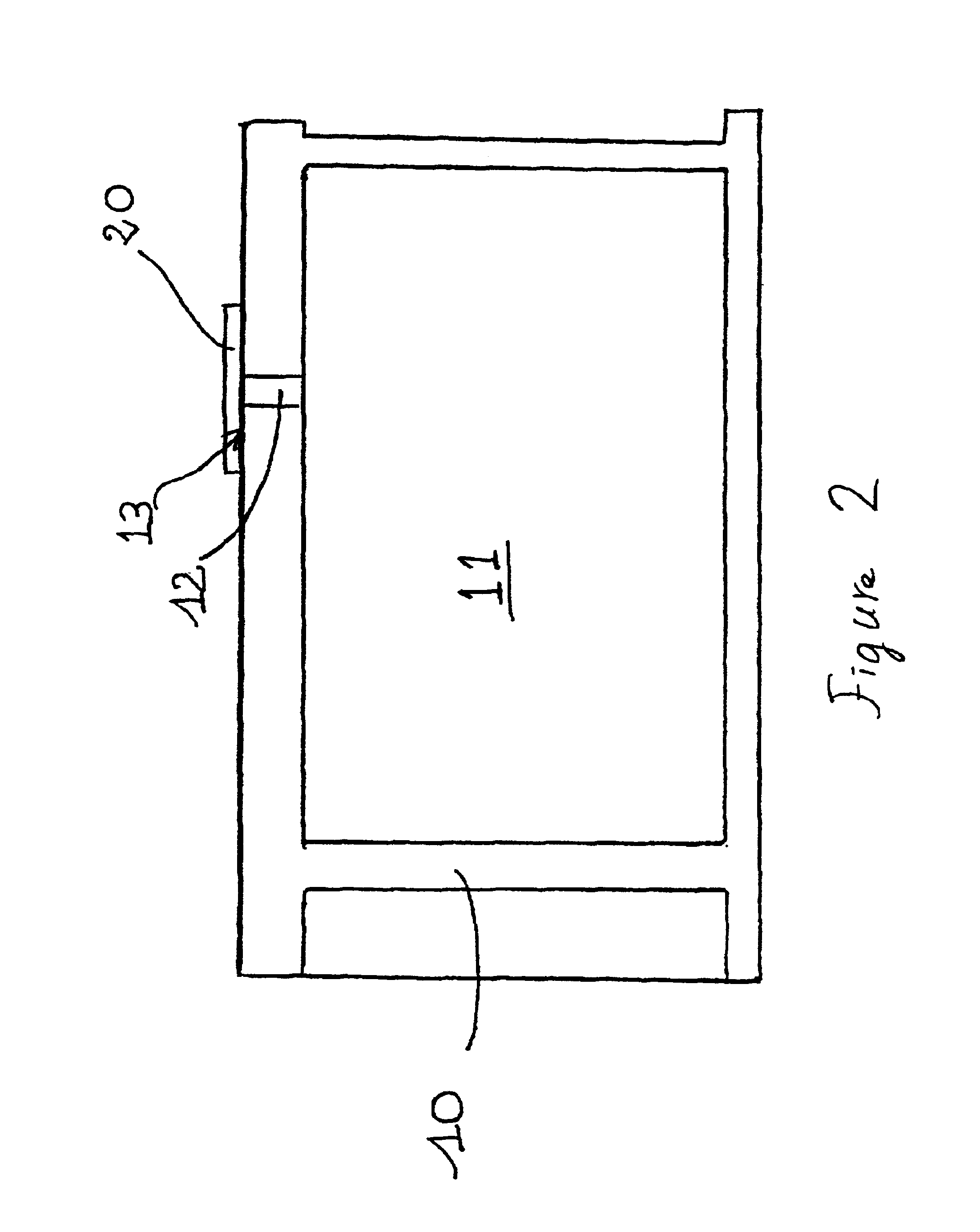
[0035]In the example embodiment illustrated in FIG. 1, a reservoir 11 is disposed in a safety support 10 of known type. The document EP 0 796 747 describes an example of such a support. In particular, it comprises cavities or recesses provided mainly to minimize weight and / or heating. One, or preferably several reservoirs 11 are disposed in the cavities and distributed circumferentially around the support. Advantageously, the reservoir is made using a material that can withstand a certain amount of deformation. Thus, if the support is subjected to a load sufficient to deform it, the reservoir will deform in the same way without being changed. In an advantageous example embodiment the reservoir is made of polypropylene. This provides good resistance to elevated temperatures. The reservoir could also be made from other materials such as plastics, composites, or even metals such as aluminum.

[0036]Advantageously, the height “Hreservoir” of the reservoir is smaller than the height “Hcavi...


PUM

PropertyMeasurementUnit
Temperatureaaaaaaaaaa
Melting pointaaaaaaaaaa

Abstract

A method of lubricating a tire cavity and more particularly the interface zone between a safety support and the inside the cavity of a tire enables lubricant to be dispensed in the interface zone only when the mounted assembly comprising the support, the tire and a wheel is in a runflat condition and where the non-instantaneous contact established between the inside surface of the tread and the seal allows the lubrication port to be unblocked. The invention also concerns a lubrication device and a seal enabling the method to be implemented, and a support and a reservoir enabling implementation of the method.

Description

[0001]This is a continuation of International Application PCT / EP00 / 10054, with an international filing date of Oct. 19, 2000, which further claims priority to French Application 99 / 13116, with a filing date of Oct. 19, 1999.BACKGROUND OF THE INVENTION[0002]The present invention concerns a mounted assembly comprising a wheel rim, a safety support and a tire able to roll along a certain distance at zero pressure with the inside part of the tread supported by the safety support. More particularly, the invention concerns a method for lubricating the interfacial zone between the inside part of the tire tread and the support. It also concerns a lubricating device and a seal which enables said method to be put into effect, as well as a support and a reservoir that enable the method to be implemented.[0003]Safety supports for vehicle wheels mounted with tires are well known. The document EP 0 796 747 describes an example of such a support consisting of a circular body adapted for fitting on...

Claims


Application Information

Patent Timeline
IPC IPC(8): B60C17/00B60C17/06B60C17/10B60C17/04
CPCB60C17/06B60C17/10Y10T29/49494Y10T152/10054
Inventor POMPIER, JEAN-PIERRE
Owner MICHELIN RECH & TECH SA
Why Eureka
Try Eureka