
Flexible Membrane With Valve

a flexible membrane and valve technology, applied in the field of laminate membranes, can solve the problems of increasing the height of the stack, the space consumed by the stack, and the peeling of the edge seal of the laminate membrane,

Pending Publication Date: 2021-07-08
GPI SYST AB
View PDF1 Cites 1 Cited by
  • Summary
  • Abstract
  • Description
  • Claims
  • Application Information

AI Technical Summary

Benefits of technology

The patent relates to a packaging container for sensitive materials that can be exposed to air and moisture. The container is designed to keep the contents secure, but may still experience a rising pressure during transport and storage. To prevent the seal from breaking, a valve is added to the packaging membrane, which allows excess gas to escape. However, this may cause problems during assembly of the container and make it difficult to stack the membranes. Additionally, a gastight package is beneficial for preventing air and moisture from affecting the contents, and for keeping fragrances and flavors in the package.

Problems solved by technology

However, during transport, such as at higher altitudes, and storage, for packaging containers comprising contents emitting gas, such packaging containers may experience a rising pressure relative to the ambient pressure which may cause the laminate membrane edge seal to start peeling off.
The relative increasing pressure within the packaging container may cause the laminate membrane to bulge outwardly and create a pulling force on the seal on the edge seal between the laminate membrane and the packaging container and possible break in the seal.
It has however been discover that providing membranes with valves may cause problems with stacking of the membranes prior to inserting them into the packaging container, i.e. during assembly of the packaging container.
This increases the height of the stack and consequently the space consumed by the stack.
The irregular surface caused by the fact that a valve is arranged on top of the membrane may also cause instability of the stack.

Method used


Image

  • Flexible Membrane With Valve
  • Flexible Membrane With Valve
  • Flexible Membrane With Valve

Examples


Embodiment Construction

[0048]It is to be understood that the drawings are schematic and that individual components are not necessarily drawn to scale. The packaging container, the laminate membrane and the valve shown in the figures are provided as examples only and should not be considered limiting to the invention as disclosed herein. In particular, it should be understood that the laminate membrane as disclosed herein may be applied to any packaging container where a breakable transport seal is desired in addition to the provision of a reclosable lid. Furthermore, the size and shape of the packaging container, a corresponding laminate membrane and valve may be different from what is shown in the figures. The valve may have a different size, configuration and shape.

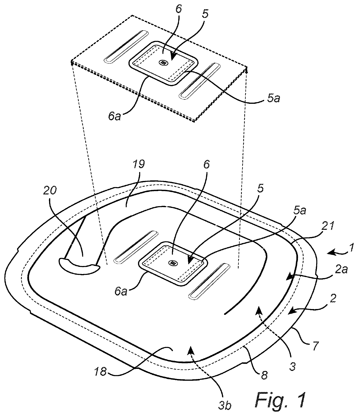
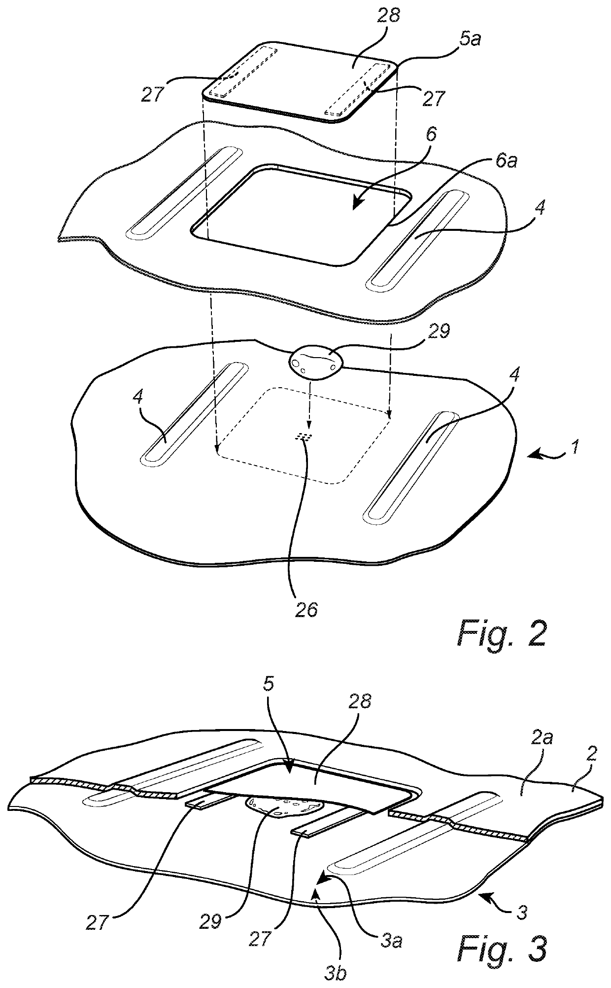
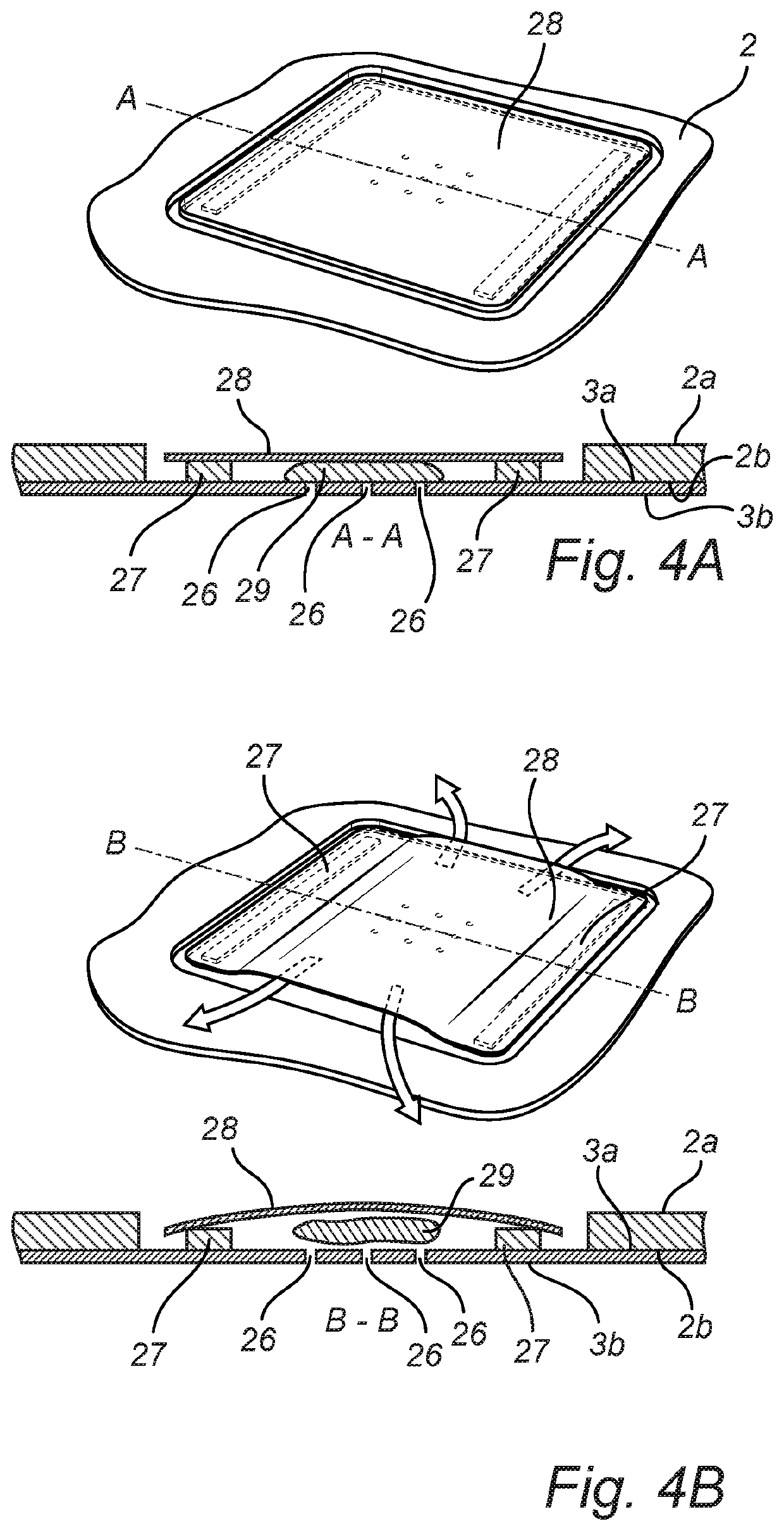
[0049]With reference to FIG. 1 there is shown a laminate membrane 1, in the form of a tear membrane 1. The laminate membrane is for sealing an inner compartment in a packaging container (not shown). The laminate membrane 1 has a top member 2 ...


PUM

PropertyMeasurementUnit
Thicknessaaaaaaaaaa
Thicknessaaaaaaaaaa
Thicknessaaaaaaaaaa

Abstract

The present disclosure pertains to a laminate membrane for sealing an inner compartment in a packaging container comprising a top member and a bottom member. The top and bottom members are laminated sheet materials. The top member has a thickness, a top member first surface and a top member second surface facing the bottom member. The bottom member has a bottom member first surface facing the top member second surface and a bottom member second surface. The laminate membrane is provided with a valve for allowing gas in the inner compartment of the packaging container to exit therefrom. The valve has a valve outer edge and is arranged on the bottom member first surface. The valve is arranged within an opening in the top member such that an opening edge encircles the valve. A surface area of the opening is greater than a surface area of the valve.

Description

TECHNICAL FIELD[0001]The disclosure pertains to a laminate membrane for sealing an inner compartment in a packaging container. The laminate membrane is a two-layer structure comprising a top member and a bottom member. The membrane is provided with a valve to allow gas to exit the closed packaging container. Disclosed herein is also a packaging container comprising the laminate membrane.BACKGROUND OF THE INVENTION[0002]Consumer goods, in particular bulk solids, are often packaged in relatively rigid paperboard packaging containers which protect the bulk solids during transport and storage at the manufacturer and retailer end and during storage and dispensing at the consumer end. One of the important factors in the area of bulk packaging containers is to ascertain that the quality of the packaged goods remains at a high level from the initial opening of the container until the packaged product has been completely consumed. The containers are usually provided with an openable and clos...

Claims


Application Information

Patent Timeline
IPC IPC(8): B65D51/16B32B3/08B32B3/26B32B15/08B32B7/12B32B15/12B32B27/10B32B29/00B65D43/16B65D51/18
CPCB65D51/1644B65D2251/0093B32B3/266B32B15/08B32B7/12B32B15/12B32B27/10B32B29/002B65D43/169B65D51/18B32B2307/582B32B2307/7242B32B2439/62B65D2251/0021B32B3/08B65D77/225B65D2577/2091B65D2577/205B65D2251/1058B32B2439/70B32B7/08B32B2307/732B32B15/20B32B29/005B32B27/08B32B2250/02B32B2250/26B32B2250/24B65D81/263B65D33/01B65D47/32B65D51/16B32B15/00B32B2439/00B32B29/00B65D65/40
Inventor HOLKA, SIMONHALLIN, MAX
Owner GPI SYST AB
Learn More