Resin seal ring and manufacturing method

a technology of resin seals and manufacturing methods, applied in manufacturing tools, machines/engines, brake systems, etc., can solve the problems of difficult to obtain a sufficient reinforcement effect in the neighborhood of the gate, the sealing ring to be formed compactly, and the configuration of the step cut portion is complicated, etc., to achieve excellent flexibility of polyether ketone resin, excellent wear resistance, and low friction coefficient

Active Publication Date: 2009-10-01
NTN CORP
View PDF5 Cites 1 Cited by
  • Summary
  • Abstract
  • Description
  • Claims
  • Application Information

AI Technical Summary

Benefits of technology

[0009]The present invention has been made to solve the above-described problems. Therefore, it is an object of the present invention to provide a resin seal ring which is flexible to such an extent that the seal ring is not broken when an expansion and a shock is applied to the seal ring in fitting the seal ring on a rotary shaft. It is another object of the present invention to provide a resin seal ring not having a weld portion that is generated in a molding operation. It is still another object of the present invention to provide a resin seal ring not having configurative disadvantages that a burr is formed and that post-processing is required. It is still another object of the present invention to provide a method of manufacturing the seal ring.
[0011]Because the seal ring is thinned with the outer diameter of the seal ring maintained, i.e., because the seal ring is thinned by expanding the inner diameter of the seal ring, the sealing performance of the seal ring does not deteriorate. The amount of a strain generated in the thin portion decreases. Consequently it is possible to increase the expansion amount of the inner diameter of the seal ring.
[0012]Since the thin portion is formed, the energy stored in the seal ring decreases when the seal ring is expanded. Consequently a smaller impact force is applied to the seal ring when the seal ring is fitted on a shaft. Thereby it is possible to prevent an impact force from breaking the seal ring.
[0015]The gate is spaced by not less than 90 degrees from the position opposed to the abutment portion. The size of the resin reservoir and the configuration of the inlet portion of the resin reservoir are adjusted in such a way that the resin reservoir and the sealing portion are charged simultaneously and completely with resin or in such a way that when the sealing portion is completely charged with the resin, the resin reservoir portion is incompletely charged therewith. Therefore in the seal ring of the present invention, it is possible to suppress generation of a burr formed by over-charging of resin and generation of a molding sink that is generated by shortage of a follow-up pressure. Further the seal ring does not have a weld portion having a low strength. Thus the seal ring is excellent in its mechanical strength and dimensional precision. Therefore the seal ring can be prevented from being broken when it is expanded to fit it on a shaft.
[0017]Owing to the use of the resin composition containing the polyether ketone resin and a predetermined amount of the spherical carbon material added thereto, the seal ring of the present invention has an excellent flexibility of the polyether ketone resin and in addition a low friction coefficient and an excellent wear resistance.

Problems solved by technology

Another problem of the seal ring having the gate for the injection molding use at the position opposed to the abutment portion is that the orientation of reinforcing fibers such as carbon fibers disposed in the vicinity of the gate is parallel with the direction of a strain-caused crack.
Thus it is impossible to obtain a sufficient reinforcing effect in the neighborhood of the gate.
In recent years, there is a tendency for the seal ring to be formed compactly because a hydraulic mechanism is becoming compact.
The above-described problem of breakage is caused by deterioration of flexibility of the composition of the seal ring containing an inorganic reinforcing material such as carbon fibers which impart a demanded high wear resistance to the seal ring.
However, the step cut portion is complicated in its configuration and demanded to have high precision to keep oil-sealing performance.
However, the seal ring has the weld portion having a low strength.
If the inner diameter of the seal ring is not more than 20 mm, the weld portion is liable to be broken by a shock applied to the seal ring when it is fitted on the rotary shaft.
However, the gate is not spaced sufficiently from the position where a large strain is generated when the seal ring is fitted on the rotary shaft.
Thus the seal ring does not have any effect of improving fittability of the seal ring on the rotary shaft or has deteriorated fittability.

Method used


Image

  • Resin seal ring and manufacturing method
  • Resin seal ring and manufacturing method
  • Resin seal ring and manufacturing method

Examples


examples 1 through 4

and Comparison Examples 1 through 4

[0099]15 wt % of carbon fiber (CF) (HTA-CMF-0160-OH produced by Toho Rayon Inc.) and 15 wt % of PTFE KTL-610 produced by Kitamura Inc. were added to 70 wt % of PEEK resin (PEEK 150P produced by Victrex Inc.). After these components were mixed with one another by using a Henschel mixer, resin pelletized by using a biaxial kneader was used as the material, for the seal ring, to be injection-molded.

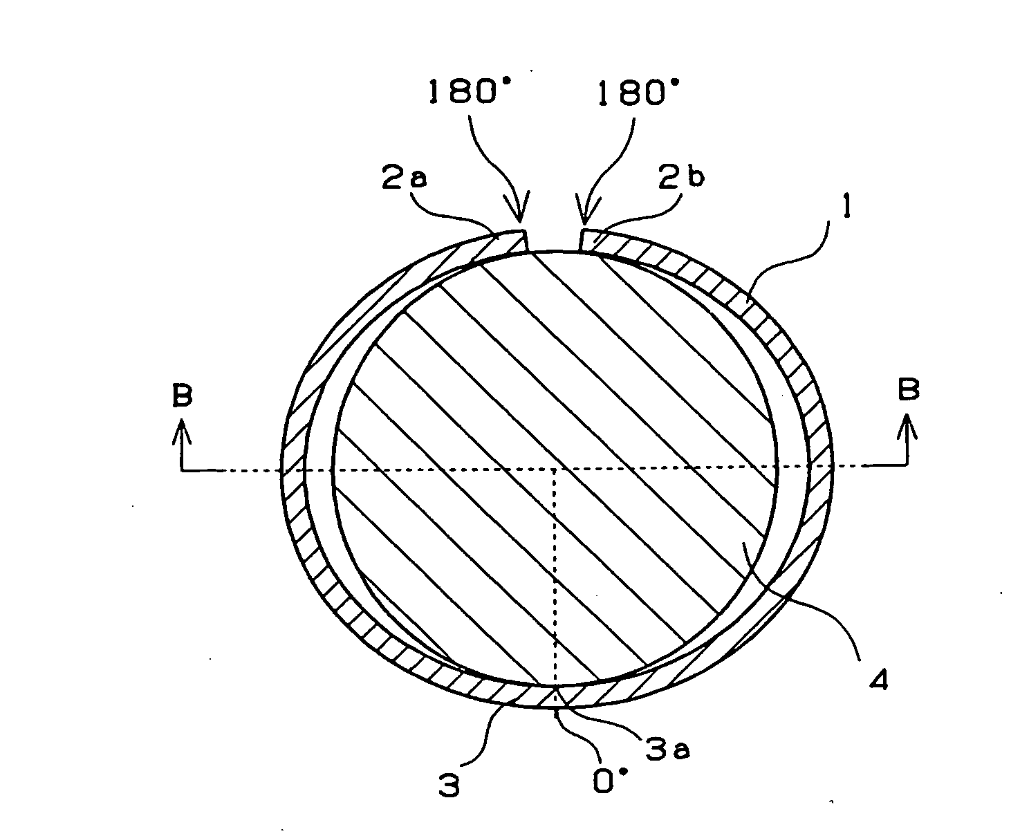
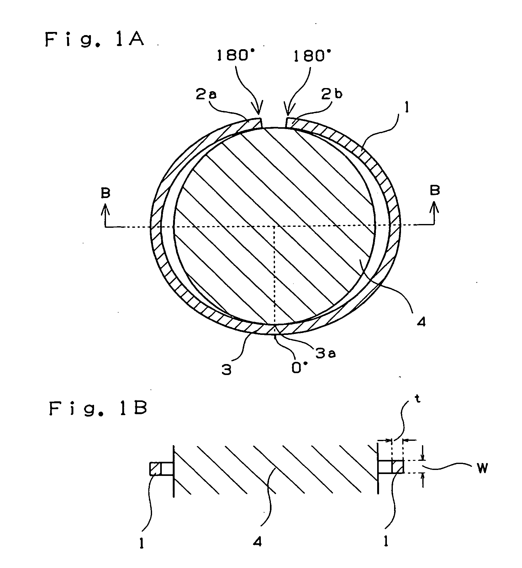
[0100]A die configured as shown in table 1 was prepared. Using the die, the material was injection-molded to obtain a seal ring whose thin portions are symmetrical with respect to the position opposed to the abutment portion shown in FIG. 3A. The diameter of the gate of each of the examples and the comparison examples was set to 0.6 mm.

[0101]Whether each seal ring passed the examination was evaluated by measuring the expansion amount of the inner diameter thereof by using a tapered jig having a length of 30 cm, a diameter of 11 mm at a smaller-diameter side...

examples 5 through 8

and Comparison Examples 5 through 7

[0105]The resin material of each of the examples 5 through 8 and the comparison examples 5 through 7 was prepared by adding 15 wt % of carbon fiber HTA-CMF-0160-OH (produced by Toho Rayon Inc.) and 15 wt % of PTFE KTL-610 (produced by Kitamura Inc.) to 70 wt % of PPEK 150P (produced by Victrex Inc.). After these materials were mixed with one another by using a Henschel mixer, the mixture pelletized at 360° C. by using a biaxial kneader was injection-molded at a resin temperature of 380° C. and a die temperature of 180° C.

[0106]The seal ring die used in the examples and the comparison examples was provided with a resin reservoir. The outer diameter of the die was 15 mm. The gate position could be disposed at any desired positions of the inner peripheral side. A telescopic construction was adopted for the resin reservoir to alter the volume thereof. The position of the resin reservoir was fixed to a position of δ=20 degrees. Molding operation was per...


PUM

PropertyMeasurementUnit
angleaaaaaaaaaa
angleaaaaaaaaaa
angleaaaaaaaaaa

Abstract

The present invention provides a seal ring which can be prevented from being broken by an expansion and a shock applied thereto when the seal ring is fitted on a rotary shaft and does not have a configurative disadvantage such as a burr. Therefore no post-processing is required. The present invention also provides materials of the seal ring and a method of manufacturing the seal ring. The seal ring is made of resin and having two abutments confronting each other and a gate mark formed in an injection molding operation.

Description

BACKGROUND OF THE INVENTION[0001]The present invention relates to a resin seal ring by injection molding, which is used for a hydraulic mechanism of an automatic transmission (AT), a continuously variable transmission (CVT) and a method of manufacturing the seal ring. More particularly, the present invention relates to a small seal ring, having an inner diameter not more than 20 mm, which can be incorporated in a mating shaft with a high mountability and a method of manufacturing the seal ring.[0002]Nowadays an oil-sealing ring for sealing a hydraulic oil used much in the automatic transmission and the continuously variable transmission is formed by injection-molding a mixture of polyether ketone resin, a reinforcing component such as carbon fiber, a solid lubricant such as polytetrafluoroethylene (PTFE) resin, and the like. An abutment portion consisting of adjacent abutments is formed on the oil-sealing ring by cutting a portion thereof. Agate into which resin is injected is forme...

Claims


Application Information

Patent Timeline
Patent Type & Authority Applications(United States)
IPC IPC(8): F16J9/12B29C45/40B29C45/00F16J9/28
CPCB29C45/0046F16J9/28B29L2031/26
Inventor SHIMAZU, EIICHIROUEMURA, KEITAROUEGAMI, MASAKI
Owner NTN CORP
Why Eureka
Try Eureka