Clamping device for machine tools

a technology for clamping devices and machine tools, which is applied in the direction of turning machine accessories, tailstocks/centres, manufacturing tools, etc., can solve the problems of increasing the overall dimension and the number of parts of the clamping device, and achieves the effect of effectively using a free space, avoiding interference between the ball screw and the movable carriage, and simplifying the overall structure of the devi

Inactive Publication Date: 2005-09-20
DMG MORI SEIKI CO LTD
View PDF13 Cites 25 Cited by
  • Summary
  • Abstract
  • Description
  • Claims
  • Application Information

AI Technical Summary

Benefits of technology

[0007]The present invention has been proposed to overcome these drawbacks. An object of the invention is to provide a clamping device for machine tools which is capable of ensuring the fixing force for the tailstock while maintaining a compact device which has a reduced number of parts.
[0011]According to the clamping device of the present invention, a wedge-shaped fitting surface is formed at each mutually opposed portion of the stationary fitting member and the movable fitting member so that fixed member, which is fixed to the fixed bed, and the movable fitting member, which is mounted on the movable carriage, are able to fit together and separate, by advancing and retreating movements of the movable fitting member. Therefore, the movable carriage can be reliably fixed to the fixed bed without a large increase in the force necessary to move the movable fitting member toward the fitting or clamping direction.
[0012]Further, by virtue of the wedging action of the wedge-shaped fitting surfaces of the stationary fitting member and the movable fitting member when they are fit together, the drive structure can be simplified since the movable fitting member is driven in advance and retreat motions by a simple mechanism. As a result, the device as a whole can be made compact and the number of parts involved can be reduced.
[0014]Further, a recessed portion may be formed at a shoulder of the recessed portion of the fixed bed. The shoulder portion includes a stepped portion having the stationary rack fixed thereto. A ball screw can be disposed in the recessed portion for moving the movable carriage in a manner known in the art. The stationary rack can be disposed by effectively using a free space while avoiding interference between the ball screw and the movable carriage. Thus, the overall structure of the device can be simplified.

Problems solved by technology

This structure requires an increased number of pistons to ensure the fixing force, thereby causing an increase in the overall dimension and the number of parts of the clamping device.

Method used


Image

  • Clamping device for machine tools
  • Clamping device for machine tools
  • Clamping device for machine tools

Examples


Embodiment Construction

[0020]Embodiments of the present invention are described below with reference to the accompanying drawings.

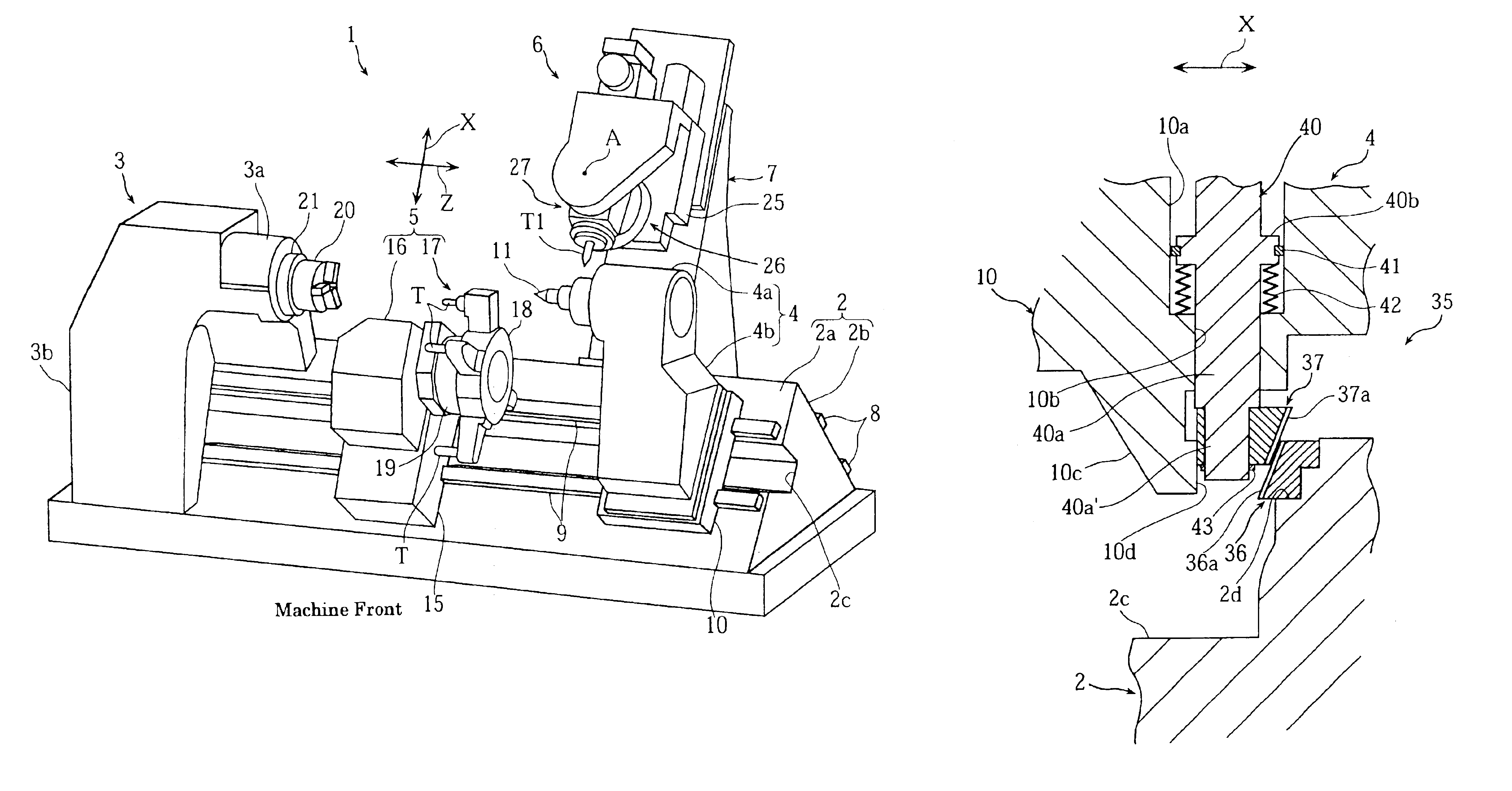
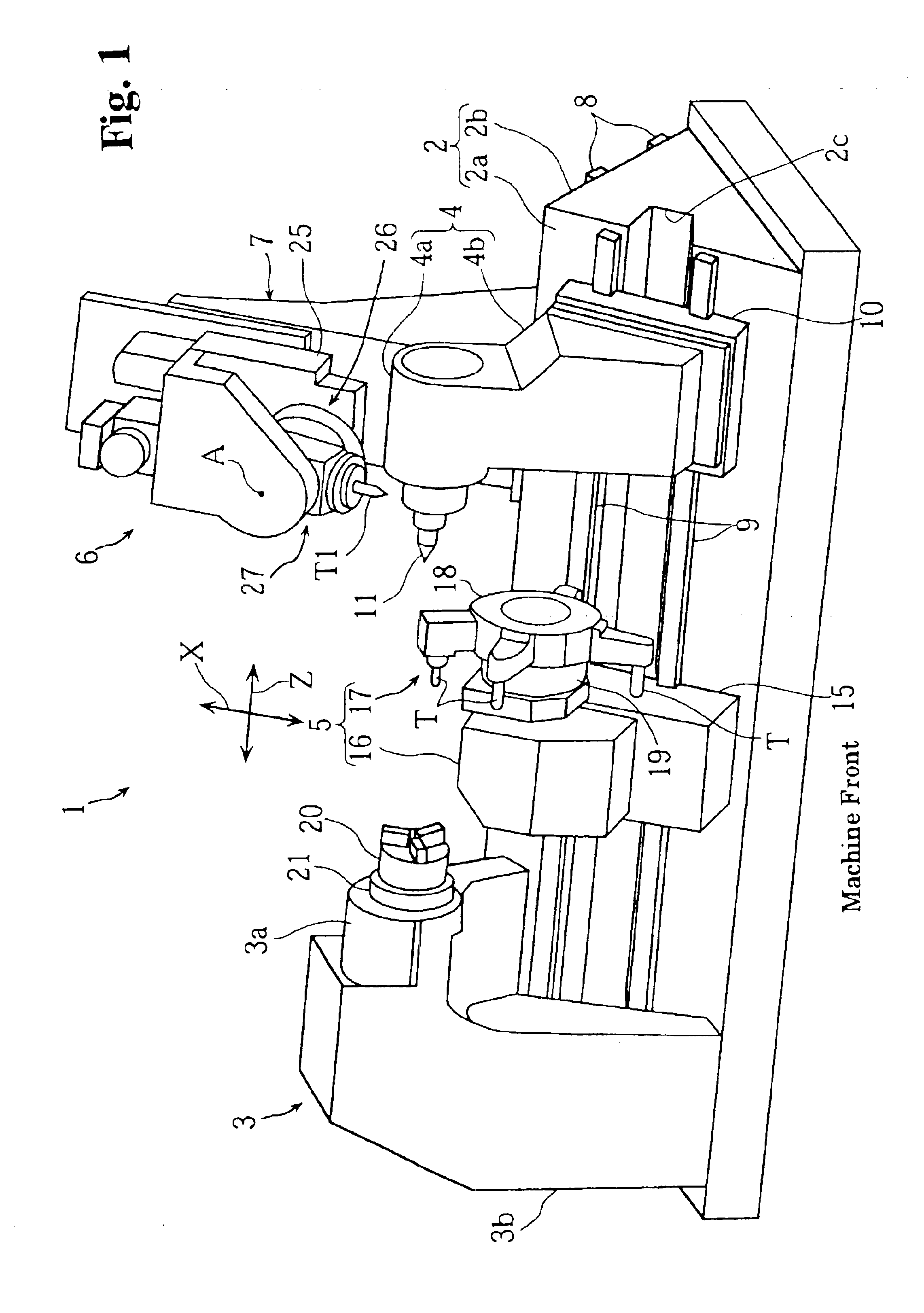
[0021]Referring to the figures, a combined machining lathe 1 has a fixed bed 2 which is formed into a triangular-prism shaped structure having two mounting surfaces including a forward-tilted sloping surface 2a and a rearward-tilted sloping surface 2b as can be seen in a perspective view shown in FIG. 1. As viewed from the machine front, a headstock 3 is disposed at a left-side longitudinal end portion of the forward-tilted sloping surface 2a of the fixed bed 2. A tailstock 4 is disposed on the right-side end portion. A lower tool rest 5 is disposed on the forward-tilted sloping surface 2a between the headstock 3 and the tailstock 4 while an upper tool rest 6 is disposed on the rearward-tilted sloping surface 2b.

[0022]The headstock 3 is composed of a spindle portion 3a for rotatably supporting a spindle 21 having a chuck 20 for grasping a workpiece, and a base portion 3b exten...


PUM


Abstract

A clamping device for machine tools is disclosed that is capable of ensuring the clamping force for a tailstock while maintaining a small overall size of the device and a reduced number of parts. The tailstock (movable carriage) movably mounted on a fixed bed is clamped at a specified position to the fixed bed. A stationary rack (stationary fitting member) extending in a direction of movement is fixed to the fixed bed. A movable rack (movable fitting member) is provided on the tailstock so as to be movable in a direction transverse to the direction of movement of the tailstock. Wedge-shaped fitting surfaces are formed at mutually opposing portions of the stationary rack and the movable rack. The movable rack is driven to perform advance-and-retreat motions between a clamping position where the movable rack fits together with the stationary rack and an unclamping position where the clamping state is released.

Description

BACKGROUND OF THE INVENTION[0001]1. Field of the Invention[0002]The present invention relates to a clamping device for machine tools which have a movable carriage which is linearly movable on a fixed bed and which needs to be clamped to the fixed bed at a specified position during machining.[0003]2. Discussion of the Related Art[0004]In a lathe, for example, a headstock with a spindle fitted thereto is secured on one side of a fixed bed while a tailstock is provided linearly movable on the other side. A workpiece is retained between the tailstock and a chuck of the headstock to keep the workpiece subjected to machining. In this case, in order to prevent the workpiece from swaying, the tailstock is fixed to the fixed bed with a clamping device.[0005]Japanese Patent Laid-Open Publication No. 2000-263358 discloses a clamping device disposed in a recessed portion of the fixed bed that extends along the direction of motion of the tailstock. A force is applied to the right and left inner ...

Claims


Application Information

Patent Timeline
IPC IPC(8): B23Q1/26B23Q1/28
CPCB23Q1/28Y10T409/309912Y10T82/2574Y10T82/2566Y10T82/2577Y10T82/2564Y10T408/91
Inventor SAKASHITA, YOSHINORI
Owner DMG MORI SEIKI CO LTD
Why Eureka
Try Eureka