Automated blind cutting machine

a blind cutting machine and automatic technology, applied in the field of automatic blind cutting machines, can solve the problems of wasting resources, consuming a lot of resources, and quickly through the pre-assembled blind with little resistance, so as to reduce the amount of space needed

Inactive Publication Date: 2005-09-20
JABBARI ABBAS +1
View PDF10 Cites 44 Cited by
  • Summary
  • Abstract
  • Description
  • Claims
  • Application Information

AI Technical Summary

Benefits of technology

[0015]According to the present invention, an automated blind cutting machine is provided that comprises a framework 10, an electrical control assembly 20, an integral measuring assembly 30, a clamp assembly 40, a die assembly 50, a cutting assembly 60, a blind support base 70, and a displacement mechanism 80. The preferred invention is designed to operate by loading the blinds vertically rather than horizontally so as to reduce the amount of space needed to house the device. Furthermore, the present invention is designed to cut both vertical and horizontal blinds by having multiple dies to accommodate the various shapes of the head rails, foot rails (if applicable), and slats.
[0017]It is an object and feature of this invention to provide a blind cutting apparatus that is automated and easy to use by one of little skill.
[0018]It is another object of this invention to provide a blind cutting apparatus that has a simple structure and can be used to cut the slats and the rails of horizontal and vertical blinds to a desired length by only one cut to produce uniform cut edges on the rails and the slats.
[0019]A further object of this invention is to provide a blind cutting machine that is so designed that the cutter module thereof can be easily and quickly replaced with other cutter modules which will cut a variety of blinds.
[0020]Another object and feature of this invention is to provide a blind cutting machine that allows for the easy replacement of components thus resulting in increased productivity and efficiency.
[0021]Yet another object of the present invention is to provide a blind cutting machine for cutting slats and rails on ether end so that readjustment of mounting mechanisms or ladders is not required when sizing the blind.

Problems solved by technology

However, customers often require blinds for windows of non-standard sizes and therefore are forced to order custom blinds.
Ordering custom blinds from a factory or distributor is relatively expensive and not economical for the average customer.
Some retailers cut down pre-assembled blinds, but they use a power miter saw which cuts rapidly through the pre-assembled blind with little resistance.
However, they are so different in their cross-sectional shapes that they are usually cut with separate and different cutting apparatus, thus resulting in a waste of resources.
Additionally, for horizontal blinds, the thin and soft ladder tapes are often damaged during cutting and other fabricating processes.
Furthermore, the problem of cutting custom made blinds in a retail establishment may be further complicated by the level of skill of the retail employee who is responsible for cutting the blind.
Retail establishments often have difficultly retaining skilled personnel.
As such, the market is price sensitive and the consumer may ultimately choose an alternative window covering if required to pay exorbitant amounts for customizing services.
Customizing also requires extra time.
Many of these cutting machines have major disadvantages.
Many are complicated in structure and are composed of numerous parts.
Additionally, many of these cutting machines are very large, taking up as much as 40 linear feet of space.
Thus, the blade is usually badly worn after each cut and requires attending.
Also, no means are provided for preventing deformation of the blind during cutting.
Furthermore, a pump with long stroke is required, thus resulting in increased cost.

Method used


Image

  • Automated blind cutting machine
  • Automated blind cutting machine
  • Automated blind cutting machine

Examples


Embodiment Construction

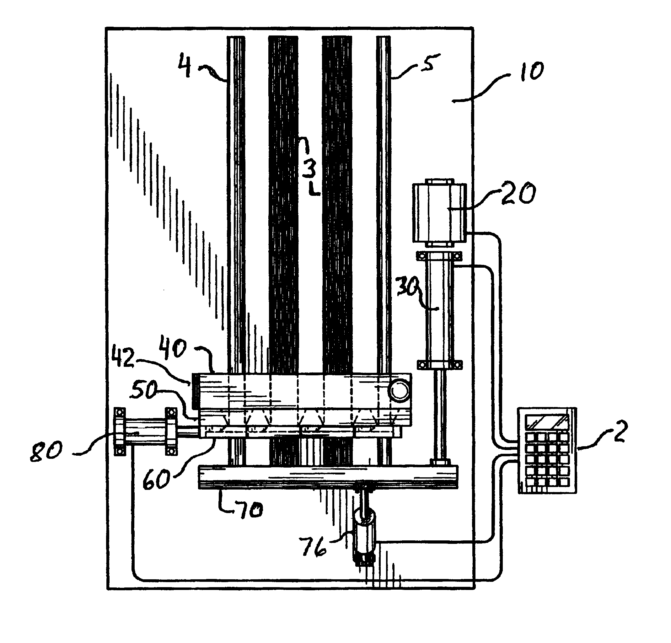
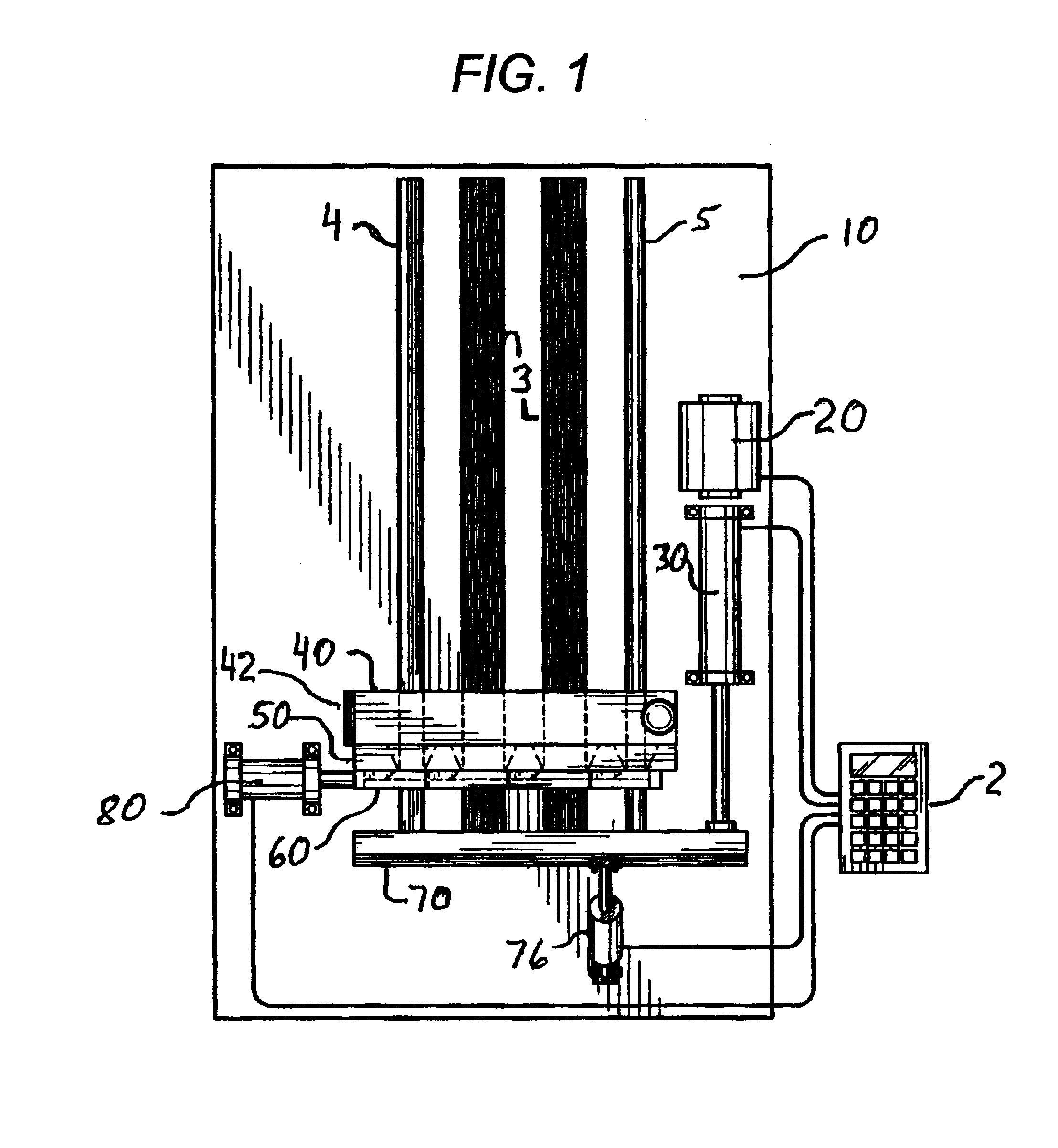
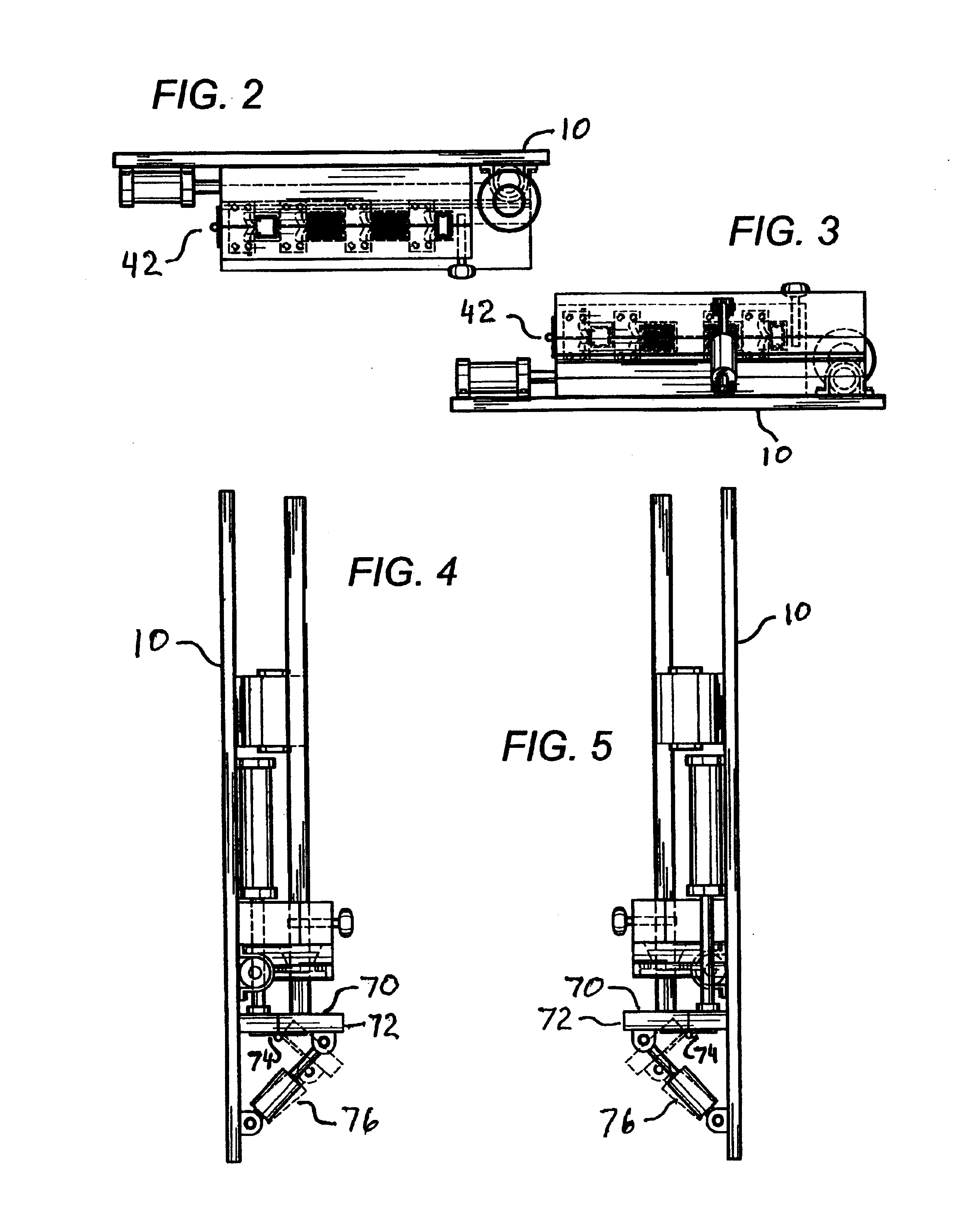
[0030]The present invention is an apparatus for cutting a horizontal or vertical blind comprising a head rail 4, a foot rail 5 (if applicable) and a plurality of slats 3. The blind cutting apparatus is preferably designed for vertical insertion of the blind into the blind cutting machine before cutting the blind. In this invention, all components of the blind are simultaneously inserted into the blind cutting machine. The sizing of the blind to be cut and the cutting of the blind are automated and do not require a skilled operator. The blind cutting apparatus comprises a framework 10, an electrical control assembly 20, an integral measuring assembly 30, a clamp assembly 40, a die assembly 50, a cutting assembly 60, a blind support base 70, and a displacement mechanism 80.

[0031]In the preferred embodiment, the framework 10 comprises an essentially vertically extending body for vertical loading of the head rail 4, foot rail 5 (if applicable), and slats 3. In a preferred embodiment, th...


PUM

PropertyMeasurementUnit
movementaaaaaaaaaa
dimensionsaaaaaaaaaa
sizeaaaaaaaaaa

Abstract

The present invention is a method and apparatus for automatically cutting a blind. The blind cutting apparatus comprises a framework, a die assembly, a cutting assembly, a clamp assembly, a blind support base, an integral measuring assembly, an electrical control assembly, and a displacement mechanism. The blind is cut to the exact dimensions by the operator who inputs the dimensions of the window and the size of the blind.

Description

CROSS-REFERENCE TO RELATED APPLICATIONS[0001]This application is a continuation-in-part of and claims priority to U.S. patent application Ser. No. 09 / 919,607, filed on Jul. 31, 2001, now abandoned.STATEMENT REGARDING FEDERALLY SPONSORED RESEARCH[0002]Not applicable.BACKGROUND OF THE INVENTION[0003]1. Field of the Invention[0004]The present invention relates generally to an automated blind cutting machine, used for cutting manufactured horizontal and vertical blinds to the desired size by those of all skill levels, and a method of operation thereof.[0005]2. Description of the Related Art[0006]A horizontal blind is a popular window covering, comprising a head rail, a foot rail, and a plurality of slats suspended horizontally from the head rail. The slats are supported by at least two parallel ladder tapes or straps which are usually suspended from the head rail and extend down to the foot rail. A vertical blind is another popular window covering, comprising a head rail and a plurality...

Claims


Application Information

Patent Timeline
Patent Type & Authority Patents(United States)
IPC IPC(8): B23D23/00B23D33/00B23D33/10E06B9/26E06B9/266
CPCB23D23/00E06B9/266B23D33/10Y10T29/39Y10T83/8858Y10T83/75Y10T83/7647
Inventor JABBARI, ABBASKASHANI, ALI A.
Owner JABBARI ABBAS
Why Eureka
Try Eureka