Modular enclosure system for electronic equipment

a technology of electronic equipment and enclosure system, which is applied in the field of modular equipment enclosure system, can solve the problems of requiring interruption of service, affecting the service life of equipment, and requiring replacement enclosures or additional ones, and achieves the effects of reducing installation costs, simple, reliable and relatively inexpensive, and reducing installation costs

Inactive Publication Date: 2005-09-20
EMERSON NETWORK POWER ENERGY SYST NORTH AMERICA
View PDF11 Cites 94 Cited by
  • Summary
  • Abstract
  • Description
  • Claims
  • Application Information

AI Technical Summary

Benefits of technology

[0008]There are a number of advantages, features and object achieved with the present invention which are believed not to be available in earlier related devices. For example, one advantage is that the present invention provides a modular system that allows each module to be handled by a single technician using a standard two-wheel hand dolly. The services of a crane are not required. Another object of the present invention is to provide a modular enclosure system that can be assembled and expanded at a site and without requiring the use of adhesives or sealants. A further advantage is that the doors, side panels and other parts of the enclosure can be changed or replaced without disconnection of any of the electronics protected by the enclosure or without interruption of the services provided by the electronics. Thus, the integrity of the system is maintain...

Problems solved by technology

Because of their size and weight, a crane is usually required to complete installation, and expansion of enclosure space often requires a new larger enclosure or an additional new enclosure.
Replaci...

Method used


Image

  • Modular enclosure system for electronic equipment
  • Modular enclosure system for electronic equipment
  • Modular enclosure system for electronic equipment

Examples


Embodiment Construction

[0020]While the present invention is open to various modifications and alternative constructions, the preferred embodiments shown in the drawing will be described herein in detail. It is understood, however, that there is no intention to limit the invention to the particular forms disclosed. On the contrary, the intention is to cover all modifications, equivalent structures and methods, and alternative constructions falling within the spirit and scope of the invention as expressed in the appended claims.

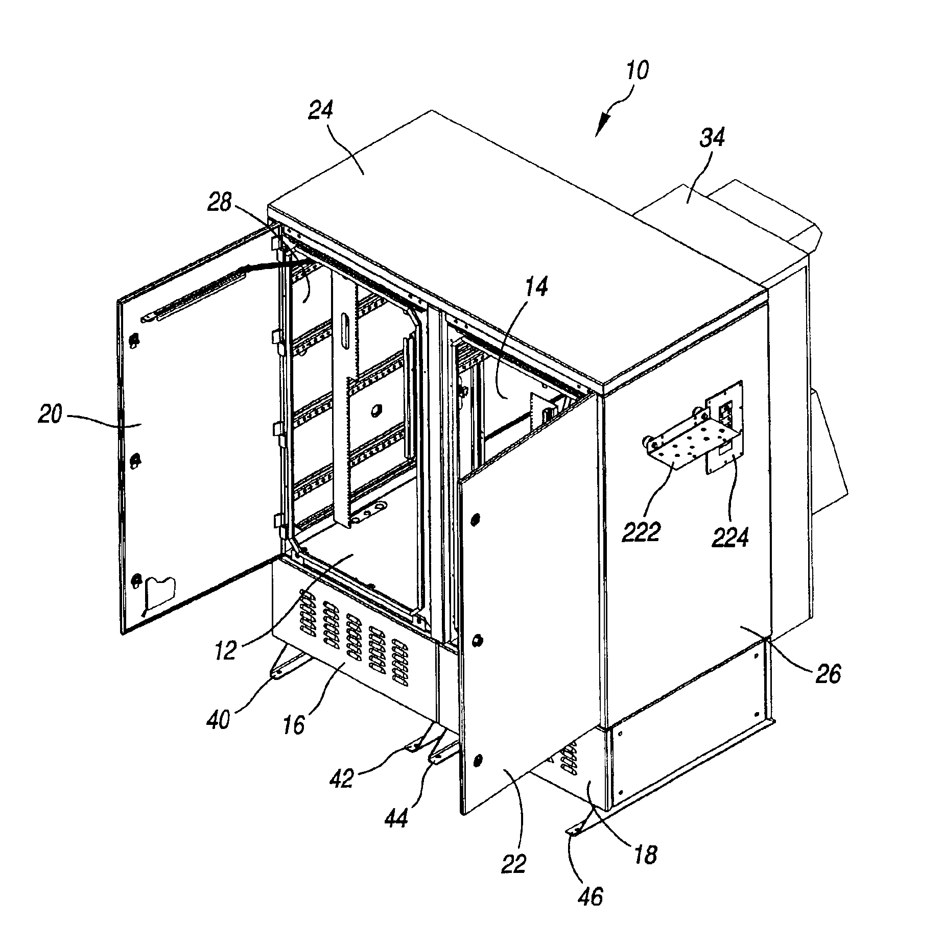
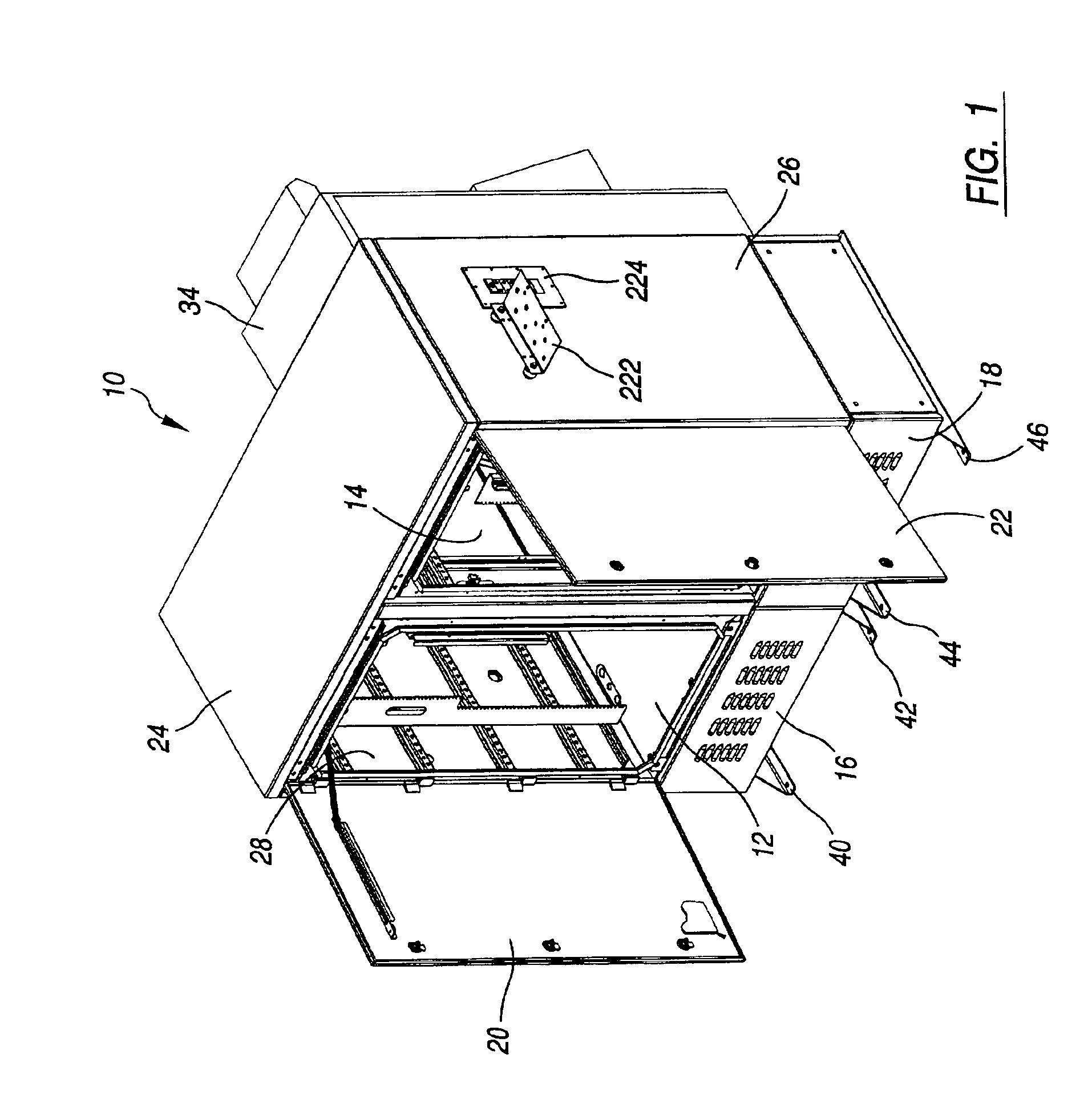
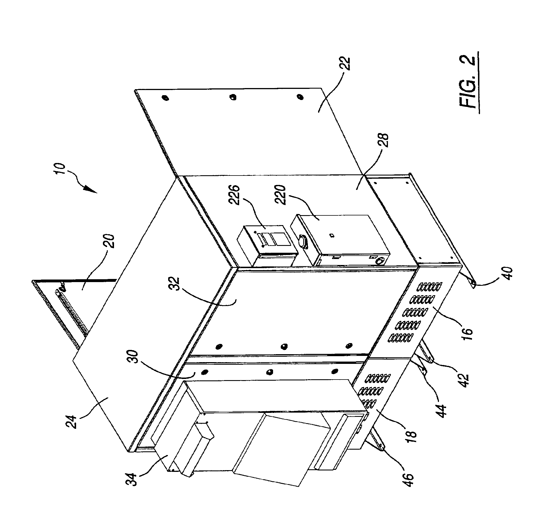
[0021]The simplicity and relative inexpensiveness of the inventive modular equipment enclosure system may be seen by reference to FIGS. 1 and 2. There is shown a modular equipment enclosure system 10 of the present invention configures with two modules or segments. The enclosure system 10 includes two chambers 12, 14 for electronic components situated side-by-side, and placed over two side-by-side battery compartments 16, 18. A pair of open front doors 20, 22 are provided to help sea...


PUM


Abstract

A modular enclosure system for electronic equipment is disclosed as is a process for assembling such a system. The basic element of the system is a frame unit which forms a chamber of the electronic equipment. Each frame unit has front, rear and side openings. Around each opening is a flange and a push-on bulb seal. A generally rectangular cross-sectioned seal is adhered to corner posts of the frame unit. Doors are mounted to the frame unit to seal the front and rear openings by compressing respective bulb seals. Side panels are mounted to the frame unit to cover side openings of a single or multi-frame unit system and the side panel compress both types of seals mentioned above. Bridge panels connect adjoining, alinged frame units and compress the rectangular seals and also result in bulb seals mounted around adjoining side openings of adjoining frame units to compress each other. Battery housings, covers and skids are also connected to aligned frame units as is a single cap panel. The system is simple, economical, easy to handle, east to install and easy to expand.

Description

BACKGROUND OF THE INVENTIONCROSS REFERENCE TO RELATED APPLICATIONS[0001]Not applicable.STATEMENT REGARDING FEDERALLY SPONSORED RESEARCH[0002]Not applicable.[0003]1. Field of the Invention[0004]The present invention relates to a modular enclosure system for electronic equipment and more particularly to a modular equipment enclosure system which allows for ease of handling, installation and on-site expansion.[0005]2. Description of the Related Art[0006]Equipment enclosures are used to house sensitive electronic equipment associated with voice, data and / or video transmission. These enclosures protect the equipment against the environment as well as from tampering and vandalism. Equipment enclosures are often placed out of doors on grounded concrete pads, on rooftops, attached to billboards or poles or within mechanical rooms. Because of their size and weight, a crane is usually required to complete installation, and expansion of enclosure space often requires a new larger enclosure or ...

Claims


Application Information

Patent Timeline
IPC IPC(8): H02B1/00H02B1/50
CPCH02B1/50H02B1/308
Inventor WEBSTER, JAMES W.LOCKHART, JULIUS C.
Owner EMERSON NETWORK POWER ENERGY SYST NORTH AMERICA
Why Eureka
Try Eureka