Induction heating type fixing device for an image forming apparatus and induction heating coil therefor

a fixing device and image forming technology, applied in the direction of electric/magnetic/electromagnetic heating, instruments, electrographic processes, etc., can solve the problems of increasing the number of wiring steps, natural consumption of power, and difficulty in dealing with the end portions of the coil, so as to reduce hot offset and accurate control the surface temperature

Inactive Publication Date: 2005-09-20
RICOH KK
View PDF16 Cites 17 Cited by
  • Summary
  • Abstract
  • Description
  • Claims
  • Application Information

AI Technical Summary

Benefits of technology

[0011]It is a first object of the present invention to provide an induction heating type fixing device capable of accurately controlling the

Problems solved by technology

However, even when the fixing device is held in a stand-by state at, e.g., 120° C., it naturally consumes much power.
In an induction heating type fixing device, if the range over which an induction coil is wound differs from a sheet passing width, then so-called hot offset occurs due to excessive temperature elevation in ranges that a paper sheet does not pass.
This brings about a problem that the main

Method used


Image

  • Induction heating type fixing device for an image forming apparatus and induction heating coil therefor
  • Induction heating type fixing device for an image forming apparatus and induction heating coil therefor
  • Induction heating type fixing device for an image forming apparatus and induction heating coil therefor

Examples


Embodiment Construction

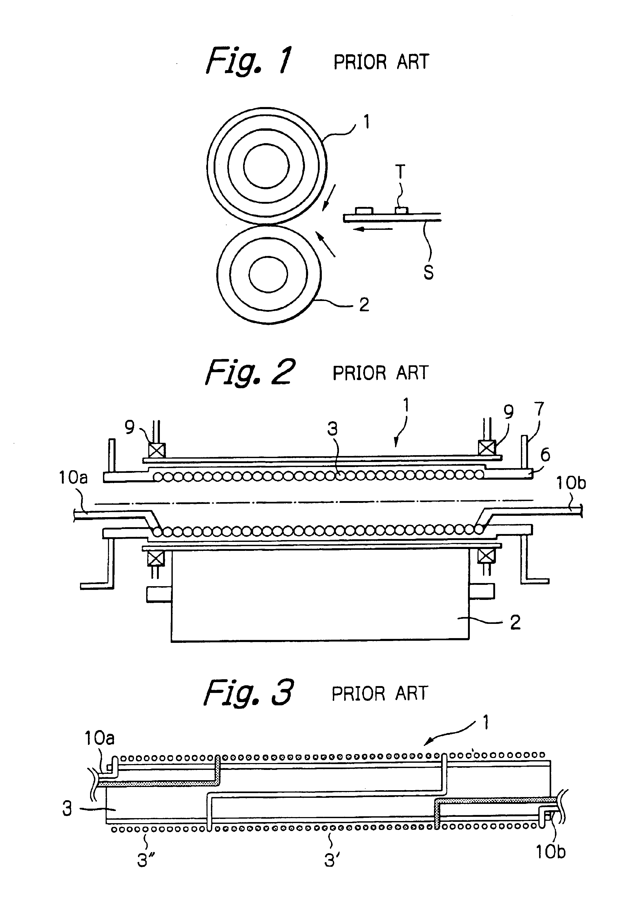
[0060]To better understand the present invention, brief reference will be made to a conventional fixing device applicable to an image forming apparatus, shown in FIG. 1. As shown, the fixing device includes a heat roller 1 and a press roller 2 pressed against the heat roller 1. The heat roller 1 and press roller 2 fix a toner image T formed on a sheet S with heat and pressure while conveying the sheet S. A halogen lamp, halogen heater or similar heating means is disposed in the heat roller 1 for heating the heat roller 1 to a preselected temperature.

[0061]It is a common practice with the above-described fixing device to heat the heat roller 1 to a preselected surface temperature, e.g., 180° C. and then maintain it at a temperature that is about 50% to 90% of the above temperature, e.g., 120° C. This allows a person to use the image forming apparatus without wasting time. However, even when the fixing device is held in a stand-by state at, e.g., 120° C., it naturally consumes much po...


PUM


Abstract

An induction heating type fixing device for an electrophotographic image forming apparatus is disclosed. An inducting heating coil has a plurality of bobbins each having a particular diameter and assembled in a telescopic manner. A particular conductor is wound round each bobbin beforehand with leads being laid inside of the conductor. The bobbin may be implemented as a plurality of bobbin members removably connected together.

Description

CROSS-REFERENCE TO RELATED APPLICATION[0001]The present application claims benefit of priority under 35 U.S.C. § 119 to Japanese Patent Application 2000-130934 filed Apr. 28, 2000, Japanese Patent Application 2000-130935 filed Apr. 28, 2000, Japanese Patent Application 2000-23 1577 filed Jul. 31, 2000, Japanese Patent Application 2000-238403 filed Aug. 7, 2000, and Japanese Patent Application 2001-050654 filed Feb. 26, 2001, and is a division 35 U.S.C. § 120 to, U.S. patent application Ser. No. 09 / 842,880 filed Apr. 27, 2001 now U.S. Pat. No. 6,753,515. The entire contents of which are incorporated herein by reference.BACKGROUND OF THE INVENTION[0002]The present invention relates to a fixing device for a printer, facsimile apparatus, copier or similar electrophotographic image forming apparatus and more particularly to an induction heating type fixing device using electromagnetic induction. Further, the present invention relates to an induction coil for use in the induction heating ...

Claims


Application Information

Patent Timeline
IPC IPC(8): G03G15/20H05B6/14
CPCG03G15/2053H05B6/14H05B6/145G03G2215/2016G03G2215/2032
Inventor MIYAHARA, AKIKOHIGAYA, TOSHIAKISUGAWARA, MASAETAKAMURA, TOMOTAKA
Owner RICOH KK
Why Eureka
Try Eureka