
Brushless permanent magnet motor with high power density, low cogging and low vibration

a permanent magnet motor and high power density technology, applied in the field of electric machines, can solve the problems of electric machines vibrating, noise, and conventional approaches to reduce vibration

Inactive Publication Date: 2005-09-20
NIDEC MOTOR CORP
View PDF13 Cites 30 Cited by
  • Summary
  • Abstract
  • Description
  • Claims
  • Application Information

AI Technical Summary

Problems solved by technology

When the electric machine rotates during operation, the electric machine vibrates, which produces noise.
The noise level of the electric machine may be an important factor in the buying decision.
Conventional approaches for reducing vibration tend to decrease power density as well.

Method used


Image

  • Brushless permanent magnet motor with high power density, low cogging and low vibration
  • Brushless permanent magnet motor with high power density, low cogging and low vibration
  • Brushless permanent magnet motor with high power density, low cogging and low vibration

Examples


Embodiment Construction

[0023]The following description of the preferred embodiments is merely exemplary in nature and is in no way intended to limit the invention, its application, or uses. For purposes of clarity, the same reference numbers will be used in the drawings to identify similar elements.

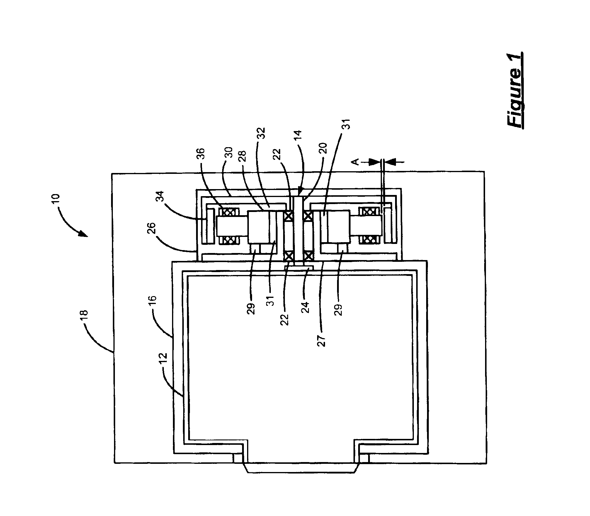
[0024]Referring now to FIG. 1, a device 10 is shown that includes a rotating member 12 that is driven by a brushless, permanent magnet (BPM) electric machine 14. An exemplary device 10 is a washing machine where the rotating member 12 is a tumbler. The rotating member 12 is rotatably supported within a cavity 16 defined by a housing 18. A shaft 20 couples the rotating member 12 to the electric machine 14. The shaft 20 is rotatably supported by bearings 22 and includes a first end coupled to the rotating member 12 by a coupling 24. A second end of the shaft 20 is coupled to the electric machine 14.

[0025]The electric machine 14 is an inside-out, brushless permanent magnet (BPM) electric machine and is supported w...


PUM

PropertyMeasurementUnit
radiusaaaaaaaaaa
angleaaaaaaaaaa
power densityaaaaaaaaaa

Abstract

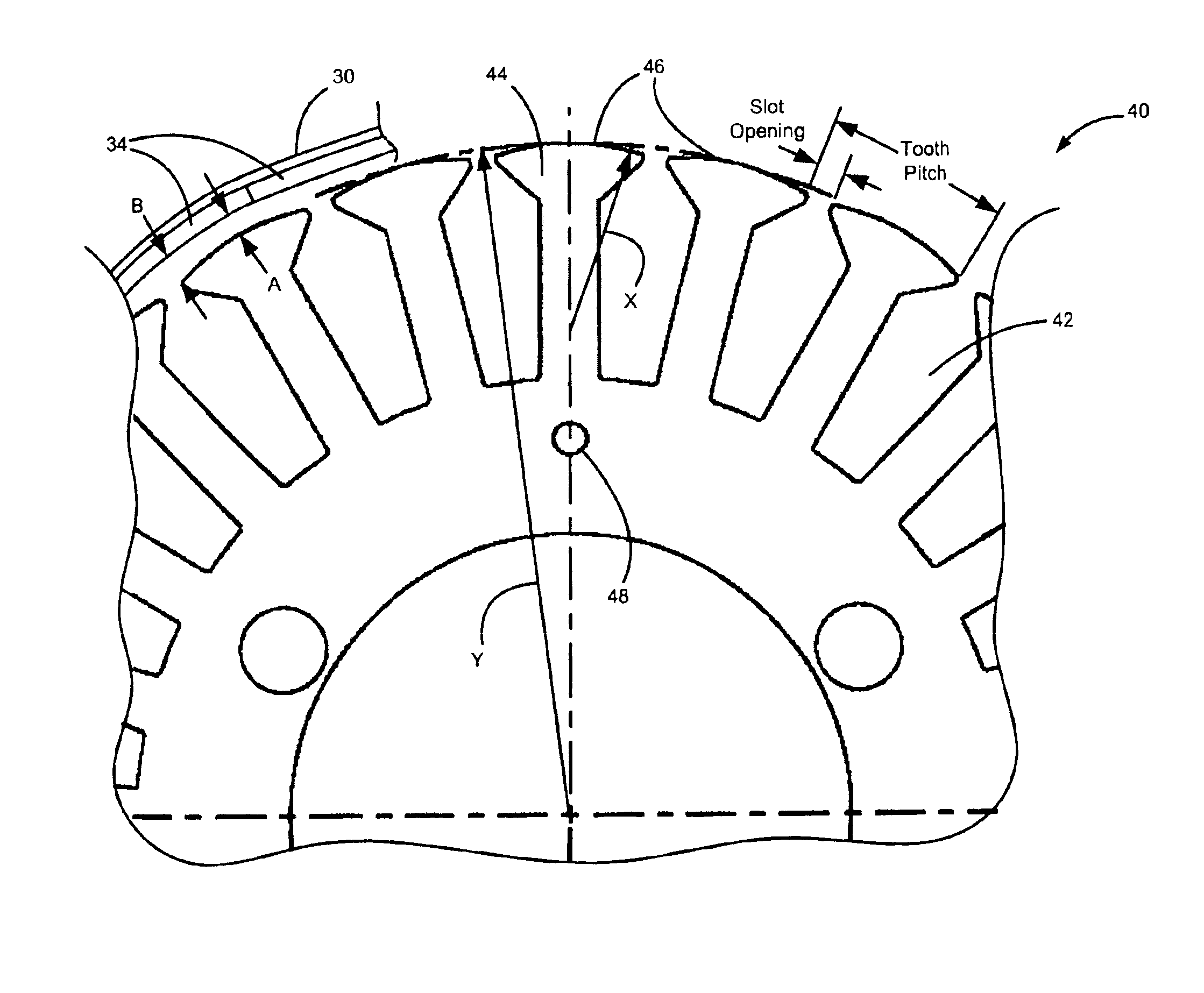
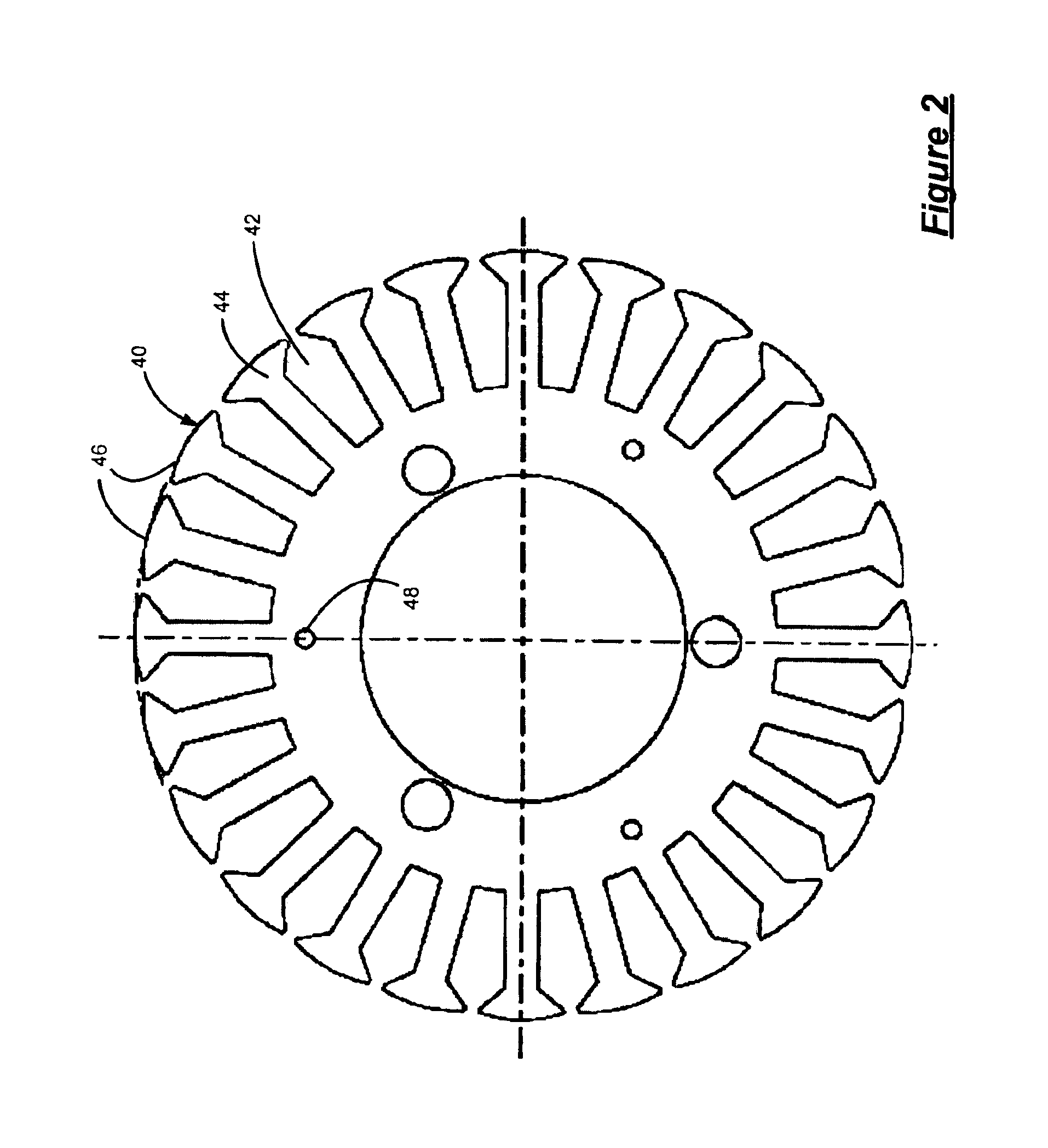
A brushless permanent magnet electric machine includes a stator assembly having a stator core that defines (12×n) slots and stator teeth having a generally “T”-shaped cross section. Winding wire is wound around the stator teeth, wherein a radially outer edge of the stator teeth define a crowned surface. A rotor includes permanent magnets defining (12±2)n poles, wherein n is an integer greater than zero.

Description

FIELD OF THE INVENTION[0001]The present invention relates to electric machines, and more particularly to brushless permanent magnet (BPM) electric machines with low cogging torque, high power density and low vibration.BACKGROUND OF THE INVENTION[0002]Electric machines, such as motors and generators, typically include a stator that is mounted inside a housing and a rotor that is supported for rotation relative to the stator. Electric machines are often integrated into devices such as appliances. The size and / or capacity of the device incorporating the electric machine may be an important factor in the purchasing decision. The size and power of the electric machine also has a significant impact on the overall size and capacity, respectively, of the device.[0003]The power density of an electric machine is defined as the ratio of the power output and the volume of electric machine. A relatively high power density (e.g., high power output relative to volume) is usually desirable. The hig...

Claims


Application Information

Patent Timeline
Patent Type & Authority Patents(United States)
IPC IPC(8): H02K29/03H02K1/16H02K21/22H02K1/06H02K1/08D06F37/30G11B19/20
CPCD06F37/304G11B19/2009H02K1/16H02K21/222H02K29/03H02K1/08
Inventor CRAPO, ALAN D.HORST, GARY E.
Owner NIDEC MOTOR CORP
Learn More