

Non-contact proximity sensor
- Summary
- Abstract
- Description
- Claims
- Application Information
AI Technical Summary
Benefits of technology
Problems solved by technology
Method used
Image

Examples
Embodiment Construction
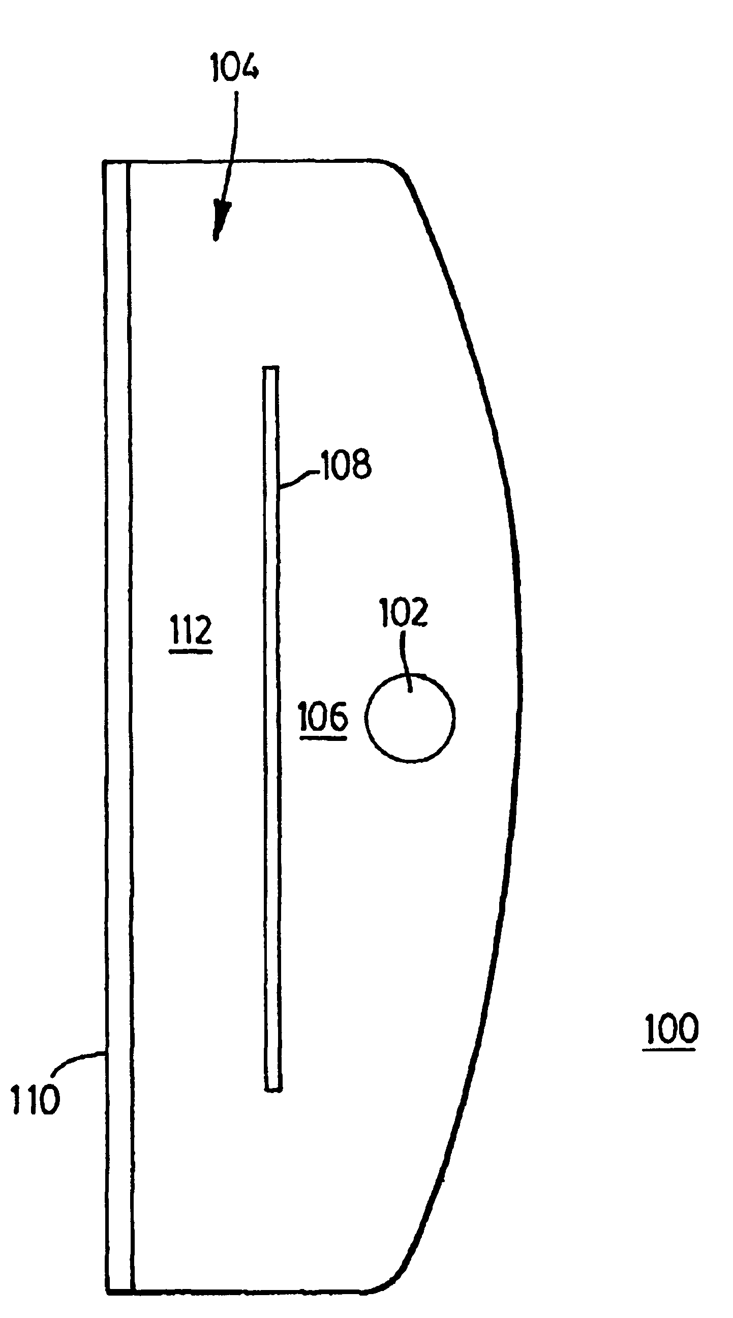
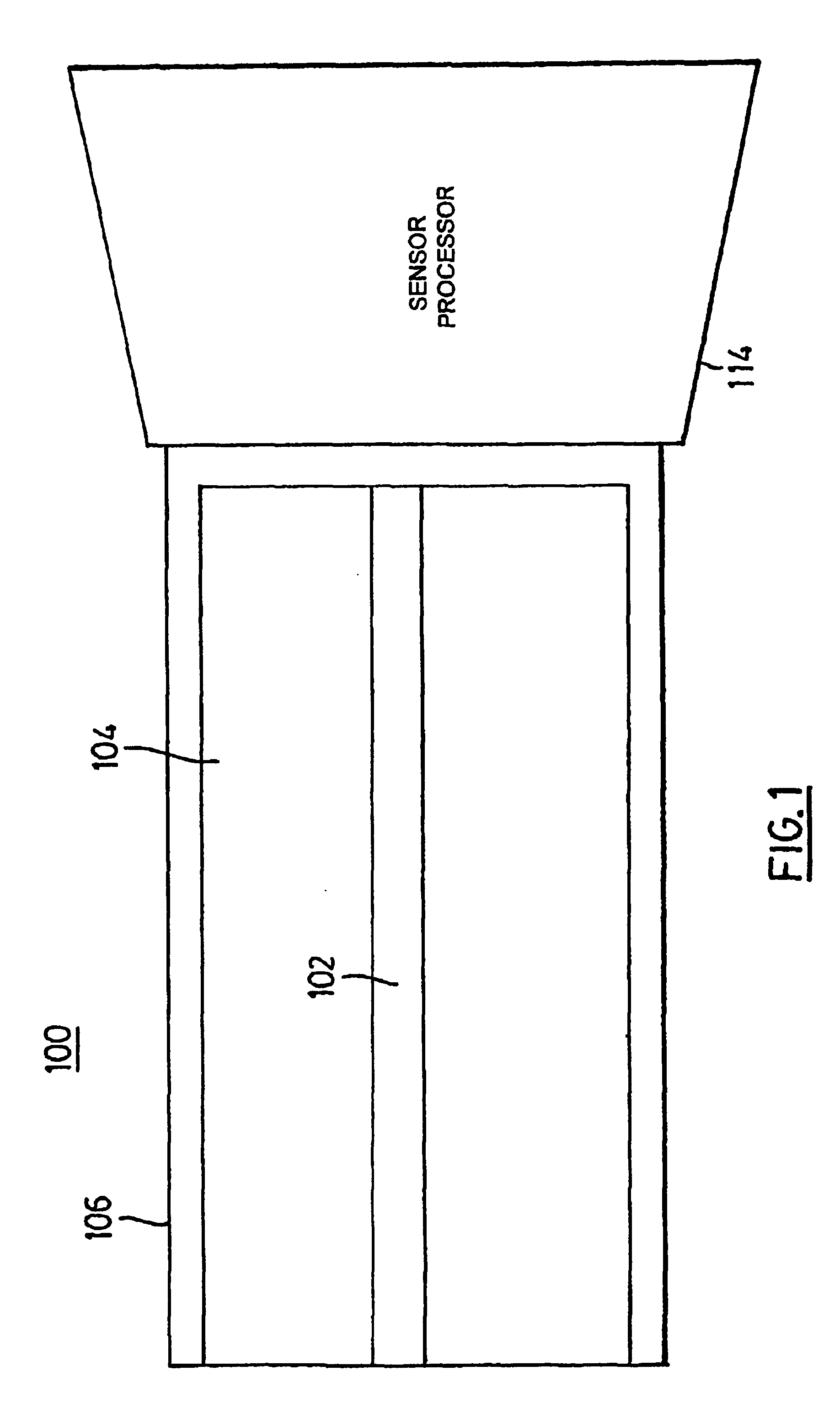
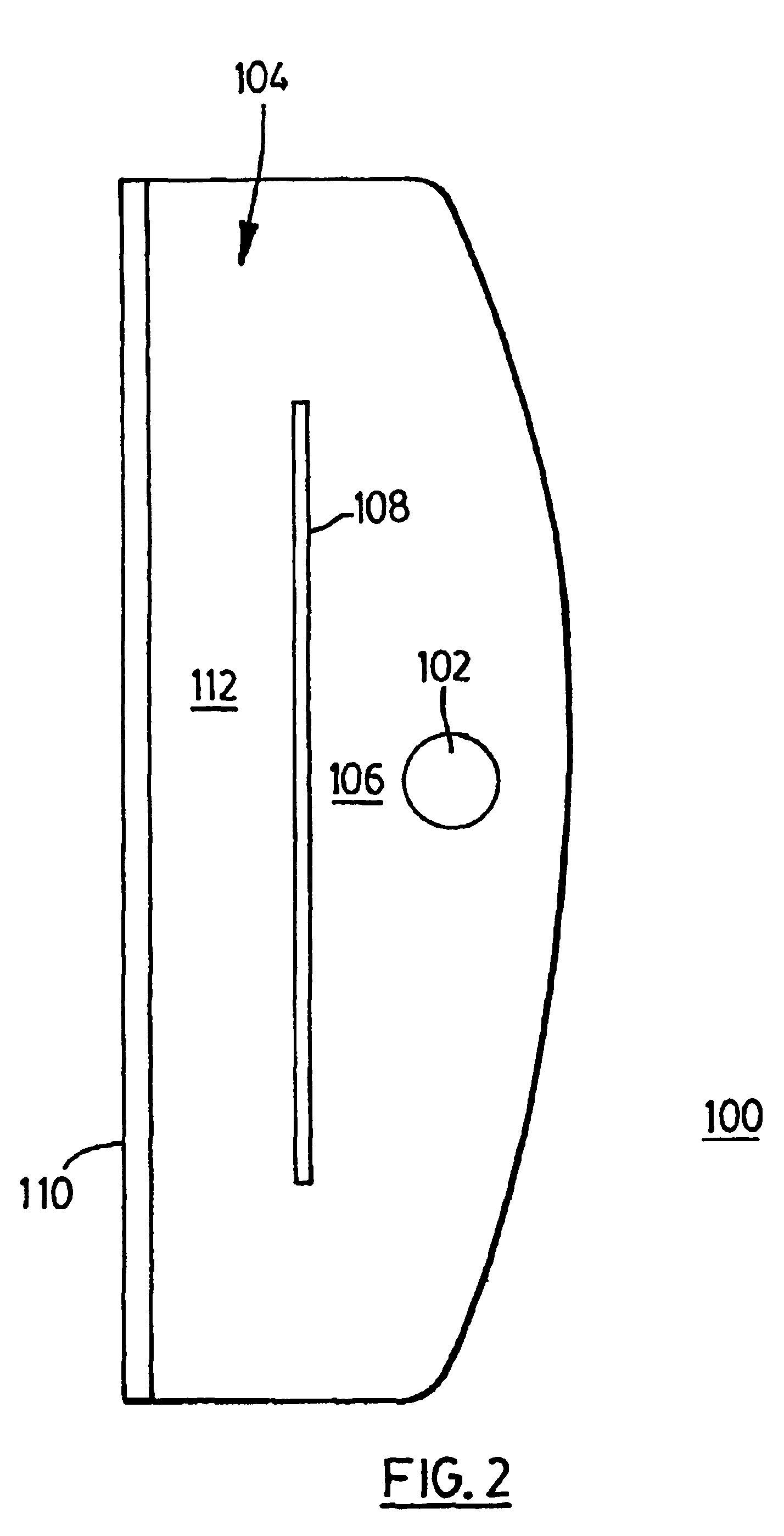
[0019]Turning now to FIGS. 1 and 2, a capacitive proximity sensor, denoted generally as 100, is shown comprising a sensor electrode 102, a capacitive shield 104 and a dielectric 106. The sensor electrode 102 is used to detect the strength of the electric field in proximity to the sensor electrode 102, and comprises a straight elongate electrically-conductive wire. Preferably, the sensor electrode 102 has a substantially circular or flat transverse cross-section. The suggested shapes for the sensor electrode 102 increase the surface area of the sensor electrode 102, thereby enhancing the sensitivity of the proximity sensor 100. However, other conductor shapes and orientations may be utilized in accordance with the application of the proximity sensor 100.
[0020]The capacitive shield 104 is configured to provide partial capacitive shielding for the sensor electrode 102. The capacitive shield 104 comprises an electrically-conductive metal sheet 108, an adhesive layer 110, and a dielectri...
PUM
 Abstract
Description
Claims
Application Information