Emissive image display apparatus

a technology of image display and emissive radiation, applied in the field of image display, can solve the problems of increasing manufacturing costs, affecting the image quality of large screen projection-type displays,

Inactive Publication Date: 2005-09-20
SONY CORP +1
View PDF13 Cites 37 Cited by
  • Summary
  • Abstract
  • Description
  • Claims
  • Application Information

AI Technical Summary

Problems solved by technology

Both of the above-mentioned emissive displays require the presence of a vacuum within the device, which can complicate manufacturing and raise costs.
As recognized herein, while effective, large screen projection-type displays suffer from the drawback of relatively low image quality, compared to the image quality afforded by a smaller emissive display.
On the other hand, current emissive display technology, as noted above, cannot easily be used to establish large screen displays owing to weight and other practical restrictions.

Method used


Image

  • Emissive image display apparatus
  • Emissive image display apparatus

Examples


Embodiment Construction

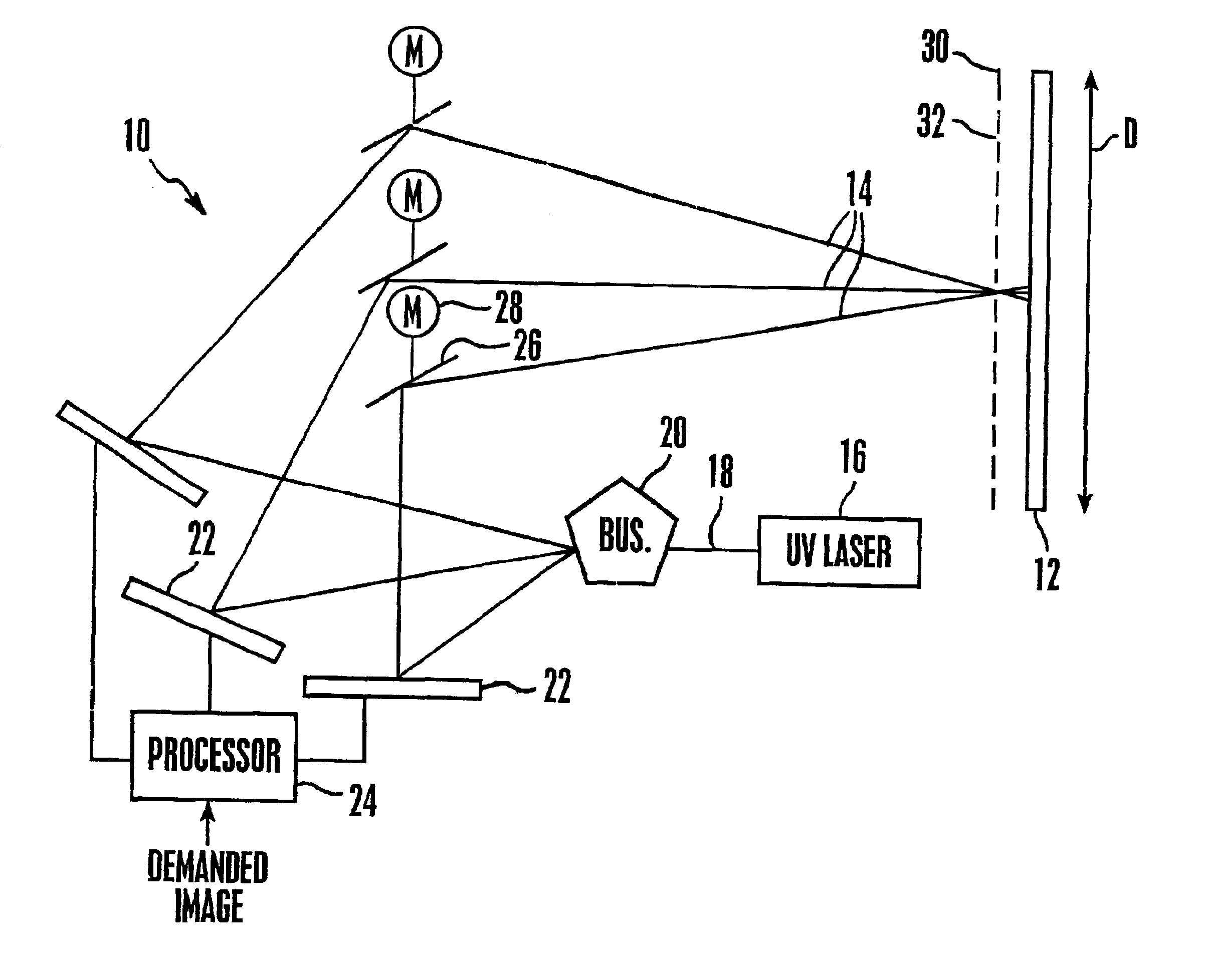
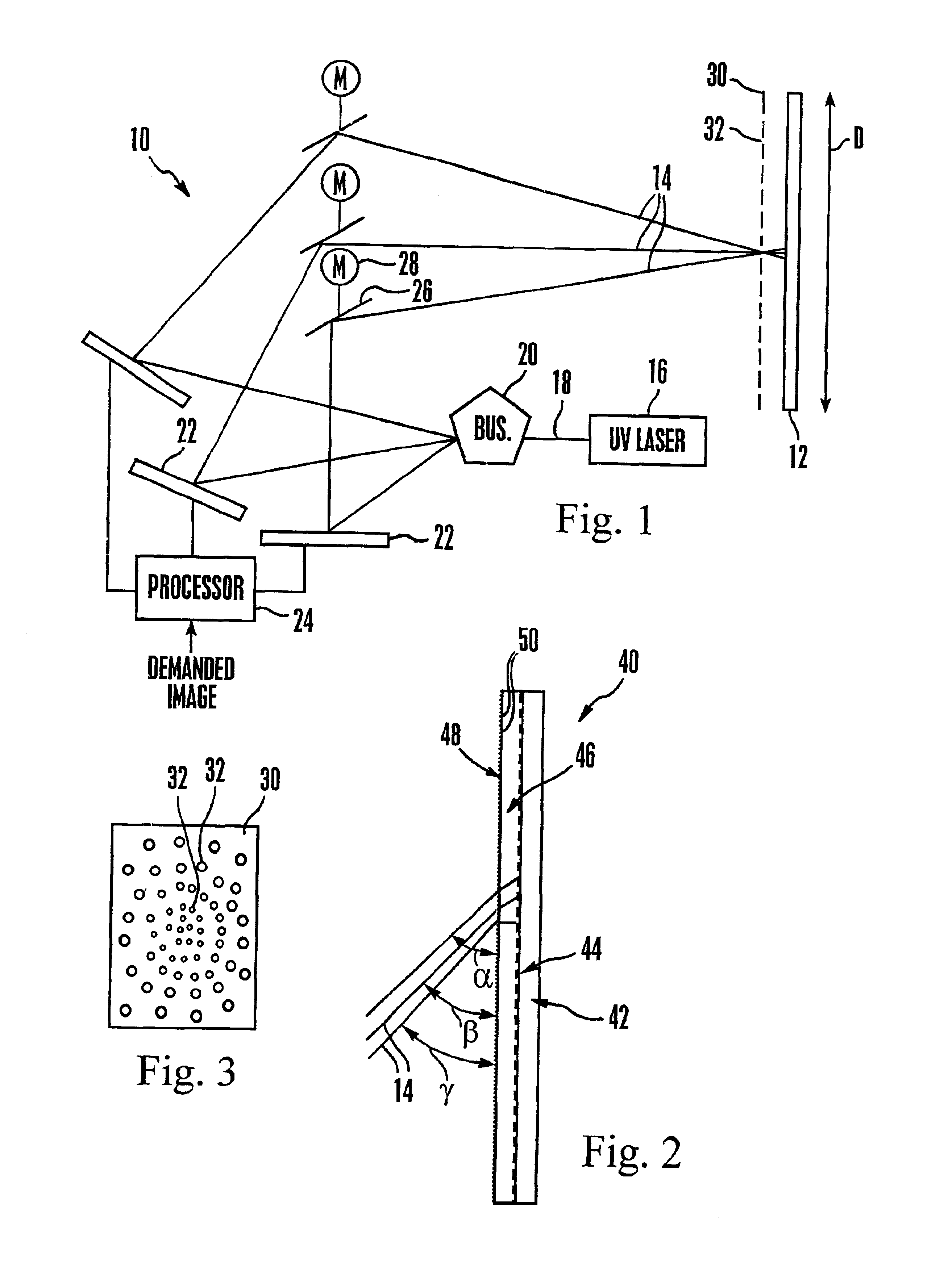
[0017]Referring initially to FIG. 1, a display apparatus is shown, generally designated 10, which includes an emissive display 12 that defines plural pixels, each pixel in turn being defined by three subpixels in accordance with emissive display principles known in the art, namely, red, green, and blue subpixels. In the non-limiting illustrative embodiment shown in FIG. 1, the display 12 is a large screen phosphor display, the pixels of which may be composed of, e.g., Zinc Sulfide. By “large screen” is meant that the operational “D” of the display 12 is at least forty inches (40″) (about one hundred centimeters) and can be sixty inches (60″) (about one hundred fifty centimeters) or more. The principles advanced herein, however, can be applied to smaller displays, as well as to other emissive displays, such as plasma displays. In any case, owing to the structure disclosed below, the display 12 operates at atmospheric pressure, i.e., the display 12 does not require a vacuum in which t...


PUM


Abstract

A large screen emissive display operating at atmospheric pressure includes pixels, the red, green, and blue subpixels of which are excited by UV laser light scanned onto the subpixels by a pixel activation mechanism. The pixel activation mechanism includes three grating light valves (GLVs) that are controlled by a processor in response to a demanded image to modulate the UV light as appropriate to produce the demanded image.

Description

FIELD OF THE INVENTION[0001]The present invention relates generally to image displays.BACKGROUND OF THE INVENTION[0002]Image displays include emissive displays, such as phosphor displays used in cathode tube-based television and computer monitors, and transmissive displays, such as projection displays used for large screen TVs. An emissive display works by emitting visible light from pixels that are excited by, e.g., electron beams or fluorescent lamps. In the case of conventional electron beam-based displays, the electron beam is scanned across the pixels as appropriate to excite the pixels to produce a demanded image. In the case of fluorescent lamp-based displays such as plasma displays, ultraviolet light from a gas discharge is directed to appropriate pixels that are physically shielded from each other, with the pixel illumination pattern necessary to produce the demanded image not being established by scanning the UV light, which is simply a discharge from the lamp, but by appr...

Claims


Application Information

Patent Timeline
Patent Type & Authority Patents(United States)
IPC IPC(8): G02B26/08
CPCG02B26/0808G02B26/0875
Inventor MORIKAWA, JOERUSS, BEN
Owner SONY CORP
Why Eureka
Try Eureka