Three-dimensional shape detection by means of camera images

Inactive Publication Date: 2005-09-20
BRAINLAB
View PDF5 Cites 100 Cited by
  • Summary
  • Abstract
  • Description
  • Claims
  • Application Information

AI Technical Summary

Benefits of technology

[0007]The present invention aims to provide a method and apparatus for detecting the shape of an object, which is capable of overcoming the aforemention

Problems solved by technology

Disadvantageously, in such methods, a complicated assignment of the positional data from the CT scan to the three-dimensional data in the operating room with the aid of the navigation system must occur prior to treatment.
On the one hand, this assignment is time-consuming since corresponding markers need to be applied manually to the skin, accessed by a referencing device, and identified.
On the other hand, the assignment is quite often inaccurate, since, for example, skin markers may move slightly out of place in the course of the referencing procedure.
Automatic referencing procedures using markers or by means of natural landmarks are highly computing-inten

Method used


Image

  • Three-dimensional shape detection by means of camera images
  • Three-dimensional shape detection by means of camera images

Examples


Embodiment Construction

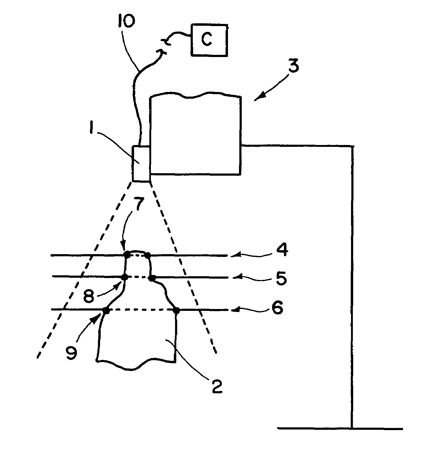
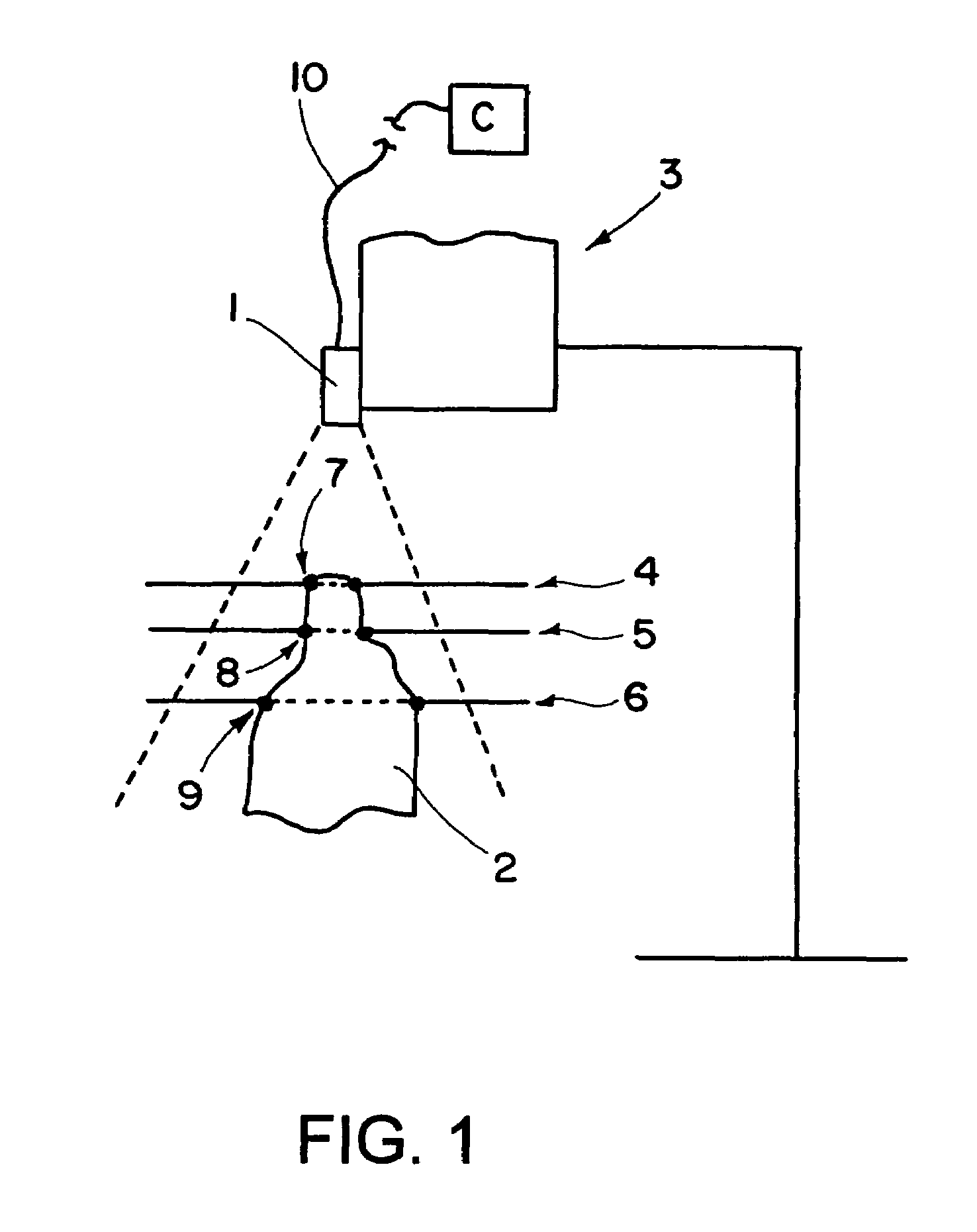
[0032]The video camera 1 produces a camera image of the object 2 in the imaging range as represented by the broken line.

[0033]The object 2 has an irregular outer shape. To detect the shape of the object 2, now, for example, one plane after the other is set sharp from the top down by the changing, more particularly by automatically changing the focussing distance of the camera 1. In the drawing, three planes 4, 5 and 6 are shown by way of example, each of which is accessed in sequence. Of course, in reality a far greater number of planes is accessed in mapping the shape, i.e., as many as is required to precisely map the shape of the object. Where highly complicated object shapes are involved, the number of focussing planes may also be automatically increased in defined distance ranges.

[0034]In accessing the planes 4, 5 and 6, as shown in the Figure, an outline of the object appears sharp in each case, this outline being represented in the drawing for the corresponding planes dotted i...


PUM


Abstract

A method of detecting the shape of an object comprises the following steps: a) producing a camera image of the object; b) mapping an outline of the object, which appears sharp in the camera image, in a first plane by means of an analyzer connected to the camera; c) altering the focusing distance of the camera; d) mapping a sharp outline of the object in a second plane by means of the analyzer; e) repeating steps b) to d) until a sufficient number of outlines has been mapped so that the three-dimensional shape of the object can be established. Also disclosed is an apparatus for implementing the method.

Description

BACKGROUND OF THE INVENTION[0001]1. Technical Field[0002]The present invention relates to a method and an apparatus for detecting the shape of an object.[0003]In many applications it is important to precisely know the outer shape of an object. One such application is, for example, in the field of medical technology. Patients are scanned, e.g., by means of computer tomography (CT), to determine the location of a tissue change in the body or in a body part prior to undergoing surgery or radiotherapy. During this, markers or emphasized points on the body part are included in the scan, the positional data of which is used later in a surgical navigation system, which monitors the treatment room during the operation in order to assist the surgeon or radiotherapist.[0004]2. Description of Related Art[0005]Disadvantageously, in such methods, a complicated assignment of the positional data from the CT scan to the three-dimensional data in the operating room with the aid of the navigation sys...

Claims


Application Information

Patent Timeline
IPC IPC(8): G01B11/24
CPCG01B11/24
Inventor VILSMEIER, STEFANBIRKENBACH, RAINER
Owner BRAINLAB
Why Eureka
Try Eureka