Antenna switching apparatus

a switching apparatus and antenna technology, applied in antennas, transmission monitoring, multi-antenna systems, etc., can solve the problems of frequent control errors in antenna switching, difficult to precisely determine the quality of reception, and small diversity effect, so as to reduce noise detection sensitivity and noise detection

Inactive Publication Date: 2005-09-20
PIONEER CORP
View PDF10 Cites 32 Cited by
  • Summary
  • Abstract
  • Description
  • Claims
  • Application Information

AI Technical Summary

Benefits of technology

[0014]The present invention has been achieved in view of the foregoing conventional problems. It is thus an object of the present invention to provide an antenna switching apparatus which detects an antenna of good reception with higher precision and suppresses or otherwise processes control errors in antenna switching to allow receiving with the antenna of good reception.
[0017]To achieve the foregoing object, in the antenna switching apparatus of the present invention, when the noise detection sensitivity is lowered and none of the plurality of antennas is switched and selected by the switching means within a predetermined time, the detecting means raises the noise detection sensitivity.
[0018]According to this configuration, if the noise detection sensitivity of the detecting means is lowered and none of the antennas is switched within the predetermined time, the noise detection sensitivity of the detecting means is raised to more appropriate, higher one. Consequently, when all the plurality of antennas are switched due to poor reception, the noise detection sensitivity of the detecting means is lowered to more appropriate lower one. When the reception is good during the predetermined time, the noise detection sensitivity of the detecting means is raised to more appropriate higher one. As a result, the noise detection sensitivity is properly varied and adjusted to the actual reception.
[0022]According to this configuration, when all the antennas are determined to be of poor reception, an antenna which has been the first subjected to the determination (at the time when all the antennas have started being switching and selected for the determination of reception) is switched and selected as new one having a higher chance of good reception.
[0023]To achieve the foregoing object, in the antenna switching apparatus of the present invention, the detecting means lowers the noise detection sensitivity when all the plurality of antennas are switched within a predetermined time established in advance.
[0024]According to this configuration, the noise detection sensitivity is lowered when all the plurality of antennas are switched within the predetermined time. This results in a noise detection sensitivity at which appropriate noise detection can be performed on all the antennas.

Problems solved by technology

There has been a problem, however, that in making “the determination whether or not antenna switching is occurring frequently”, a reduction in the time Tch for counting the number of times M of antenna switching can cause more frequent fixing of antennas, making the diversity effect smaller.
On the other hand, if the time Tch for counting the number of times M of antenna switching is extended, it becomes difficult to determine the quality of reception precisely.
This has produced a problem of frequent control errors in antenna switching.
Moreover, the comparator 6 compares the predetermined threshold THD and the noise component Sn to determine reception quality, whereas simply comparisons between the threshold THD and the noise component Sn do not promise high-precision determinations on reception quality.
This has caused a problem of difficulty in suppressing control errors in antenna switching.
In other words, there has been the problem that simply comparing the threshold THD and the noise component Sn cannot achieve high-precision determinations on reception quality under momentary variations in the field strength of incoming waves, the influence of surrounding environment on the antennas, and so on.

Method used


Image

  • Antenna switching apparatus
  • Antenna switching apparatus
  • Antenna switching apparatus

Examples


Embodiment Construction

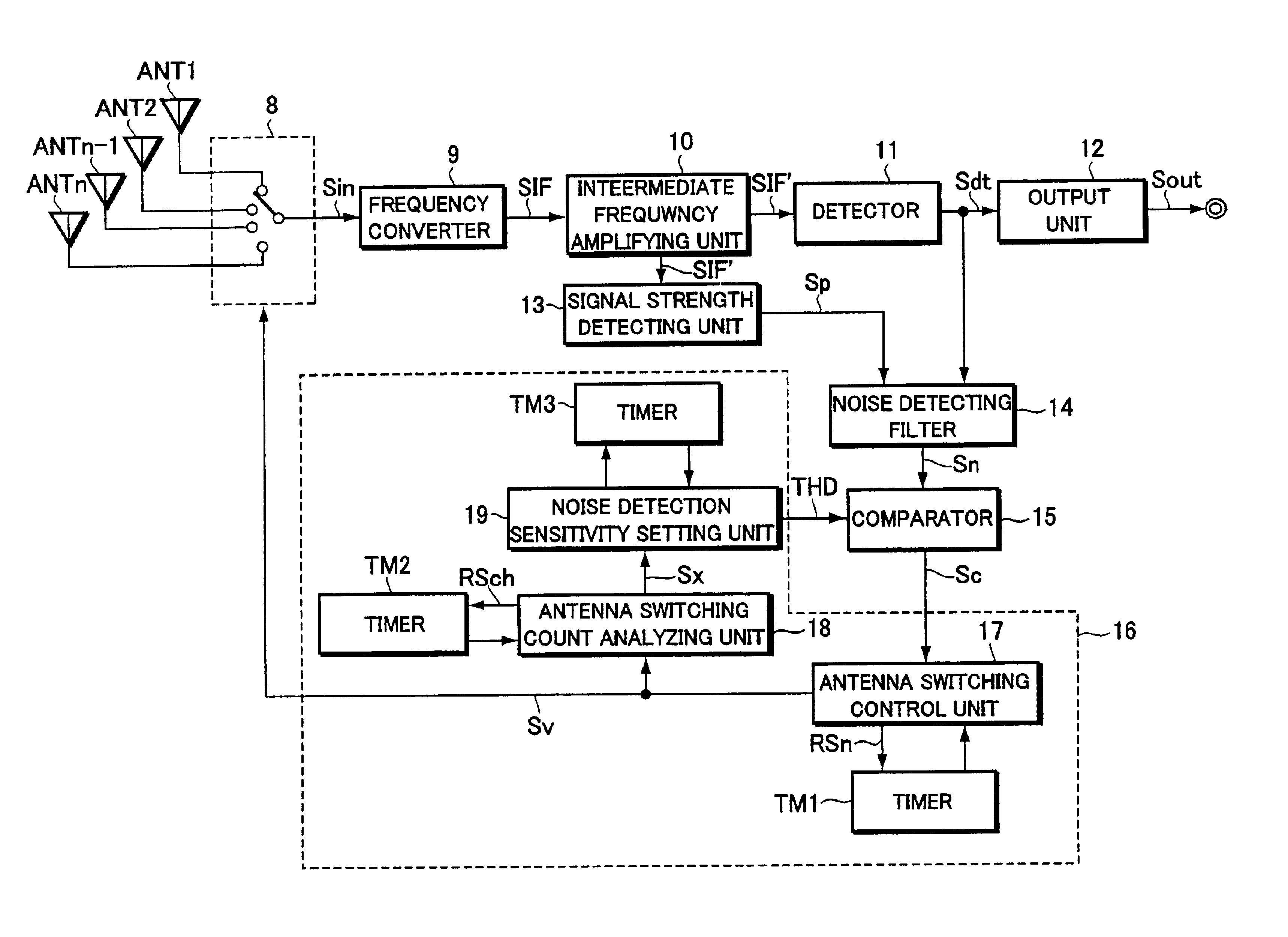
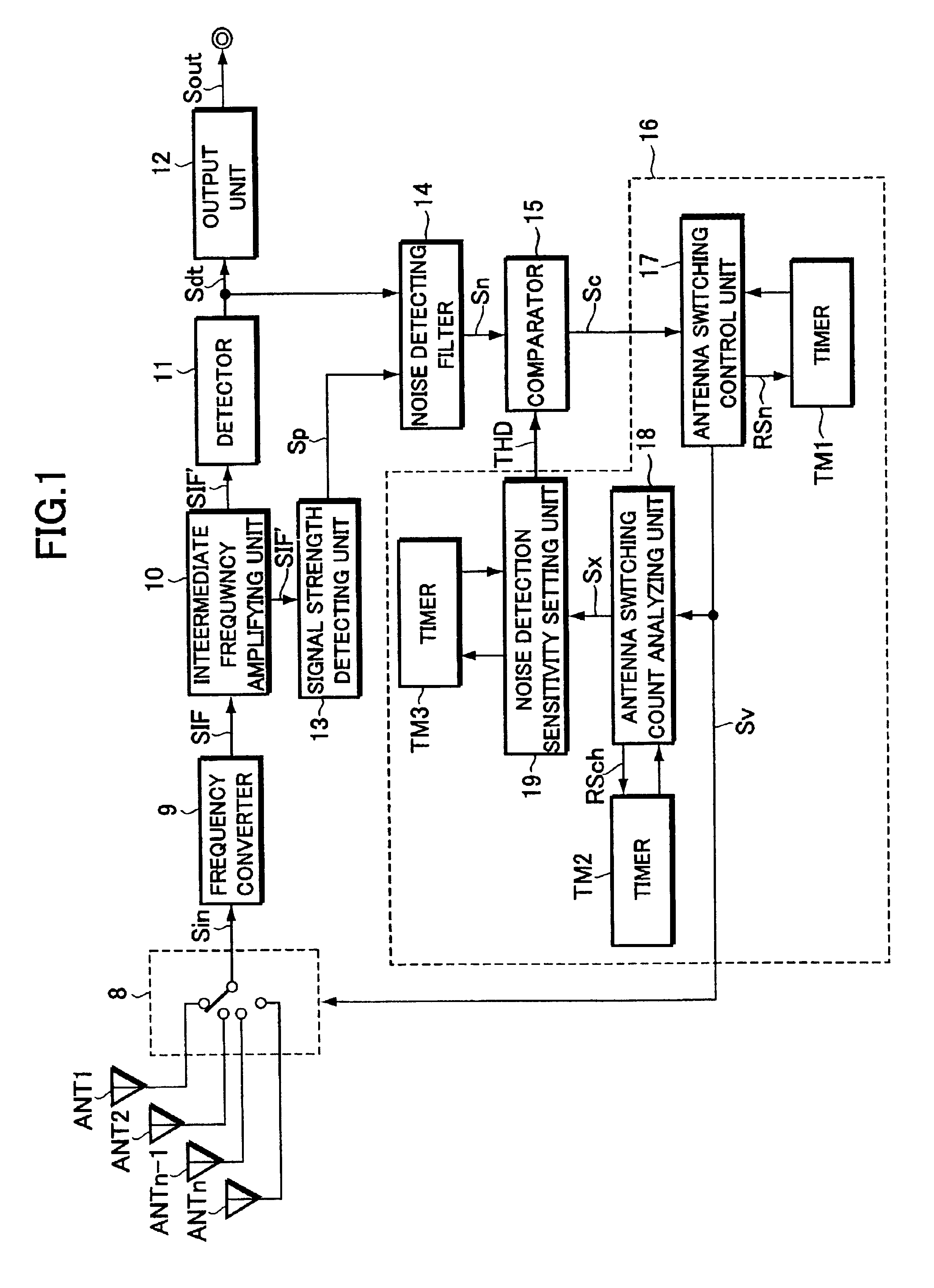
[0035]Hereinafter, an embodiment of the present invention will be described with reference to the drawings. FIG. 1 is a block diagram showing the configuration of an antenna switching apparatus of the present embodiment which is incorporated into a receiving system such as a radio receiver.

[0036]In the diagram, the radio receiver or the like is equipped with a plurality (arbitrary number) n of diversity antennas ANT1-ANTn. A switching circuit 8 is interposed between the diversity antennas ANT1-ANTn and a frequency converter 9. The switching circuit 8 makes a switching operation according to an antenna switching control signal Sv supplied from a control unit 16 (which will be described later), thereby establishing exclusive connection between any one of the antennas and the frequency converter 9.

[0037]The frequency converter 9 downconverts a high-frequency reception signal Sin supplied through the switching circuit 8 to generate an intermediate frequency signal SIF. An intermediate f...


PUM


Abstract

An antenna switching apparatus which detects an antenna of good reception with high precision and suppresses control errors in antenna switching. A comparator compares a noise component obtained from a selected antenna with a threshold for noise detection. When noise detection occurs a predetermined number of times within a predetermined time, an antenna switching control unit outputs an antenna switching control signal to switch to another antenna. If all antennas are switched within a predetermined time, a noise switching count analyzing unit outputs a sensitivity control signal, deciding that the threshold should be changed. A noise detection sensitivity setting unit, when supplied with the sensitivity control signal within a predetermined time, increases the threshold to lower the noise detection sensitivity of the comparator. When the predetermined time elapses without the sensitivity control signal being supplied, the noise detection sensitivity setting unit decreases the threshold to lower the noise detection sensitivity of the comparator. The noise detection sensitivity is thus varied and adjusted to the actual reception quality, whereby an antenna of good reception is detected with high precision and control errors in antenna switching are suppressed.

Description

BACKGROUND OF THE INVENTION[0001]The present invention relates to an antenna switching apparatus for switching and selecting a diversity antenna of good reception from a plurality of antennas properly.[0002]The present application claims priority from Japanese Application No. 2001-244732, the disclosure of which is incorporated herein by reference for all purposes.[0003]Conventionally, there has been known a diversity receiving system which has a facility to automatically switch and select a diversity antenna of good reception among a plurality of antennas so as to ensure favorable reception performance in receiving radio broadcasts such as an FM broadcast.[0004]As shown in FIG. 9, this diversity receiving system has a switching circuit 1 which is interposed between a plurality n of antennas ANT1-ANTn and an intermediate frequency signal processing unit 2. The switching circuit 1 switches and selects a single antenna exclusively so that a high-frequency reception signal Sin occurrin...

Claims


Application Information

Patent Timeline
Patent Type & Authority Patents(United States)
IPC IPC(8): H04B7/08
CPCH04B7/0814
Inventor ONO, YASUSHI
Owner PIONEER CORP
Why Eureka
Try Eureka