Method and system for monitoring a supply-chain

a supply chain and supply chain technology, applied in the field of methods and systems for monitoring a supply chain, can solve the problems of inconvenient monitoring of the supply chain, inability to monitor the supply chain, so as to eliminate much of the confusion

Inactive Publication Date: 2005-09-20
ELCOMMERCE COM
View PDF25 Cites 83 Cited by
  • Summary
  • Abstract
  • Description
  • Claims
  • Application Information

AI Technical Summary

Benefits of technology

[0007]The present invention eliminates much of the confusion which results from redesigning one or more complex legacy systems. Instead, legacy systems are left intact, and a data transfer engine (“DTE”) is installed at each site. The DTE monitors the local system continuously, and takes whatever information is available. While a complete picture of the supply chain may not be provided if not all information is available, for example, if a certain attribute is not tracked at a particular site, the DTE takes whatever data is available, cleans up the data, and formats the data into a common format acceptable to a data collection site. The DTE then transmits or uploads the data to the data collection site, which is preferably a distributor or an OEM.

Problems solved by technology

While these supply chain sites share some data, the data is typically maintained in incompatible formats in legacy databases.
Yet, in practice, how each supply chain site deals with its external environment, i.e., vendors, CMs, customers, has often been archaic and inconsistent.
Supply chain management is difficult because it depends on the axiom that a business has fundamentally correct processes.
Whether these changes are implemented by outside consultants or by in-house staff, lack of clear project goals, effective monitoring and performance review constantly plague the process.

Method used


Image

  • Method and system for monitoring a supply-chain
  • Method and system for monitoring a supply-chain
  • Method and system for monitoring a supply-chain

Examples


Embodiment Construction

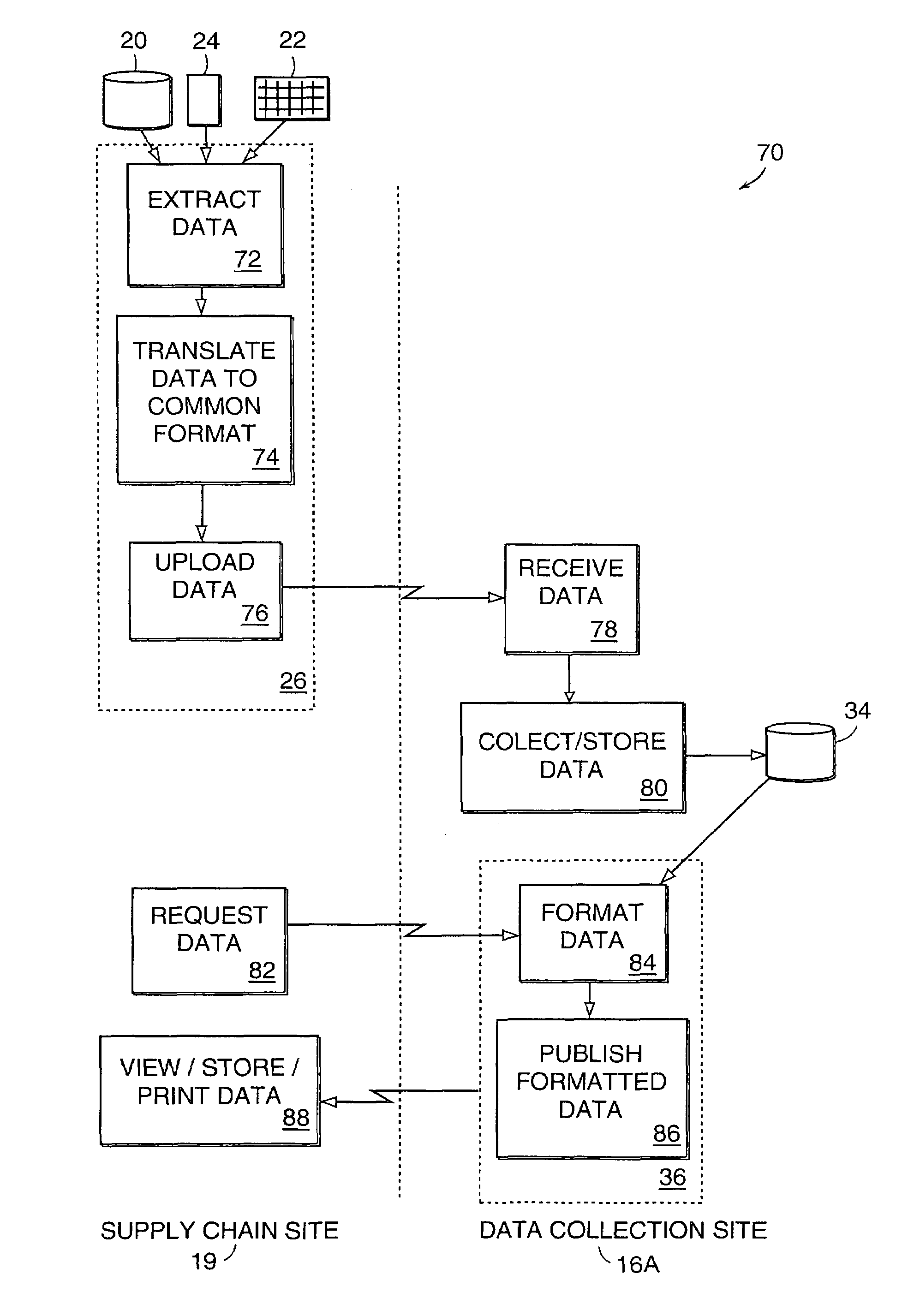
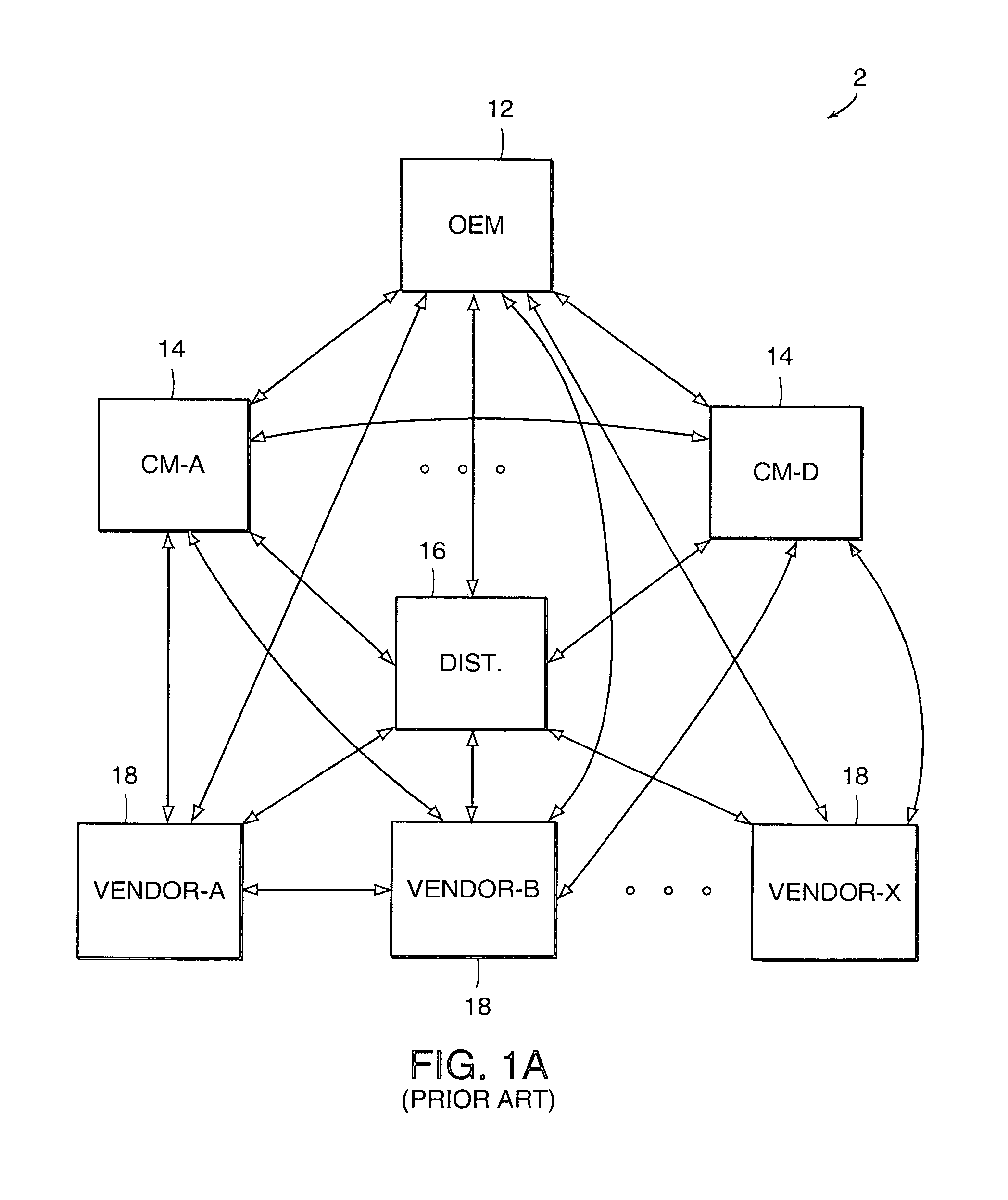
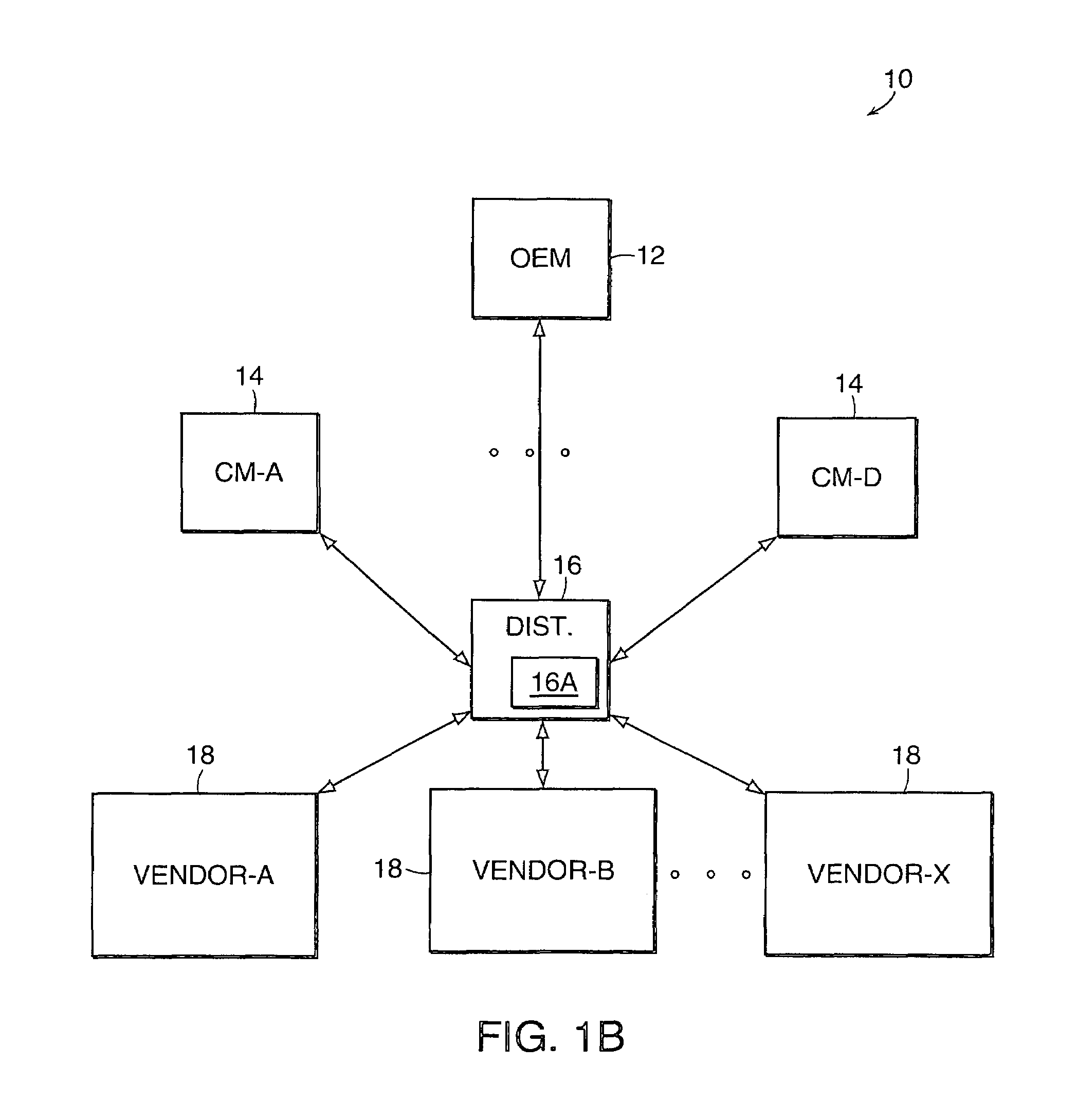
[0051]FIG. 1B illustrates a supply chain 10 environment in which the present invention is employed. An original equipment manufacturer (“OEM”) 12 designs products, assembles the products or contracts assembly out, receives sales orders (“SOs”) from customers and generates purchase orders (“POs”) to obtain the parts required to build the ordered equipment.

[0052]The POs may be sent to contract manufacturers (“CMs”) 14, who build, for example, boards which typically have 50 to 200 or more parts. The OEM 12 may contract with several CMs 14 to build the same board, and / or may contract with different CMs for different boards. Here, for example, several contract manufacturers CM-A through CM-D are depicted.

[0053]The CMs 14 themselves must obtain the required parts or components, such as resistors, capacitors, semi-conductors, knobs, indicators, hinges, switches, buttons, etc., either directly from the component manufacturers, or vendors 18, or more typically, from one or more distributors ...


PUM


Abstract

A method of monitoring supply chain activity throughout a plurality of supply chain sites includes extracting, at each supply chain site, supply-related data to be monitored. The data is maintained in plural formats at the supply chain sites, and translated the data to a common format. The extracted data is then uploaded to and collected, from each supply chain site, to a data collection center or site. Upon a user request, a portion of the collected data is formatted, at the data collection site, into one of a plurality of views, responsive to criteria selected by the user, for presentation to the user, the portion of formatted data being dependent on access rights granted to the user's supply chain site. Finally, the formatted data view is published to the user's supply chain site. The data collection center comprises a data collector in which the uploaded data is stored, and a publisher for publishing data from the data collector upon request. Each supply chain site has a data storage device for maintaining its own supply-chain data, a data transfer engine (DTE), for transferring the supply-chain data to the data collection center, input means for allowing a user to query the data collector, and a display for displaying data published by the publisher in response to a query. The inbound data received from the multiple supply chain sites is monitored at the data collection site. If a problem condition is detected, such as a forecasted or present shortage or surplus, an alert is asserted, for example, by highlighting an Alert indicator, such as an Alert tab, on a user screen. Upon selection of the highlighted Alert indicator by a user, details of the detected problem condition are displayed.

Description

RELATED APPLICATION[0001]This application claims priority to U.S. Provisional Application No. 60 / 147,670 filed on Aug. 6, 1999, and is related to application Ser. No. 09 / 544,916, filed Apr. 7, 2000, entitled METHOD AND SYSTEM FOR MONITORING A SUPPLY-CHAIN, by Brian M. Perry; the entire teachings of which are incorporated herein by reference.BACKGROUND OF THE INVENTION[0002]A typical manufacturing supply chain includes an original equipment manufacturer (“OEM”), which designs and sells equipment such as computers or other electronic equipment. To keep costs down, OEMs often contract out the manufacture of at least some of the individual components of the product, such as electronic boards, to contract manufacturers (“CMs”). The CMs must obtain the parts with which to build the boards, such as resistors and integrated circuits, which are manufactured by component manufacturers or vendors. The components are typically not sold directly to the CMs but rather are sold through distributor...

Claims


Application Information

Patent Timeline
Patent Type & Authority Patents(United States)
IPC IPC(8): G06Q10/00G11C5/00
CPCG06Q10/06G06Q10/087
Inventor PERRY, BRIAN M.
Owner ELCOMMERCE COM
Why Eureka
Try Eureka