Management of working status with large-scaled display

a large-scaled display and working status technology, applied in the field of management techniques, can solve the problems of insufficient discussion on the effective position of the display, inability to achieve the advantages of large-scaled displays, and insufficient display information to contribute to the improvement of working efficiency, etc., to achieve smooth production, smooth and quick take the required measures, and enhance the effect of production flexibility

Inactive Publication Date: 2005-05-24
SEIKO EPSON CORP
View PDF11 Cites 12 Cited by
  • Summary
  • Abstract
  • Description
  • Claims
  • Application Information

AI Technical Summary

Benefits of technology

[0030]This arrangement causes the related pieces of information to be individually displayed on the large-scaled displays in the respective areas, while enabling the important pieces of information to be shared in another area in the factory. Here the assembly area is not restricted to the main assembly line of the products. When there are a plurality of assembly areas including subassembly areas of parts, the input terminal and the large-scaled display should be located in at least one of these assembly areas. In such cases, it is naturally preferable that the input terminal and the large-scaled display are located in a specific area having the most significant effects on the total productivity.
[0031]The another area may be other than the three areas mentioned above. For example, the another area is a management section that manages a production flow in the factory. As discussed previously with regard to the third arrangement, the application of displaying the important pieces of information in the management section enables each manager in the management section to flexibly manage the production according to the situation without delay.
[0032]The another area may be an upstream process area corresponding to an upstream process, which is prior to a process performed in the area where the transmitted information is input. The application of displaying the working status of a downstream process area in the upstream process area ensures the smooth production in the whole factory. In one example, it is assumed that there is a delay in shipment of a certain product, although the required quantity of the product for shipment is fulfilled. In such cases, the situation is displayed in each upstream process area, for example, the assembly area, as the information from the product storage area. This enables each upstream process area to prepare for expected modification of the production plan according to the change of the shipment plan and deal with actual modification of the production plan without much confusion. The application of displaying the information in the upstream process area enables the upstream process area to smoothly and quickly take required measures against a change of the situation, thus enhancing the flexibility of production.

Problems solved by technology

In some cases, it is rather difficult for the worker to check the display during an operation, so that the display of information does not sufficiently contribute to the improvement in working efficiency.
No sufficient discussion has been made on the position of the display effective for operations that require movements.
The conventional display does not allow the advantages of the large-scaled display to sufficiently contribute to transmission of information between the different sections.
It is accordingly difficult for all the workers in each section to obtain the consistent information without delay.
Such deficiency of the information transmission may interfere with smooth operations in the respective sections.
Various pieces of information may thus not be sufficiently used for the production management.
Since each manager requires a diversity of information, it is unpractical and inefficient to display all such information on the large-scaled display.

Method used


Image

  • Management of working status with large-scaled display
  • Management of working status with large-scaled display
  • Management of working status with large-scaled display

Examples


first embodiment

A. Application to Storehouse

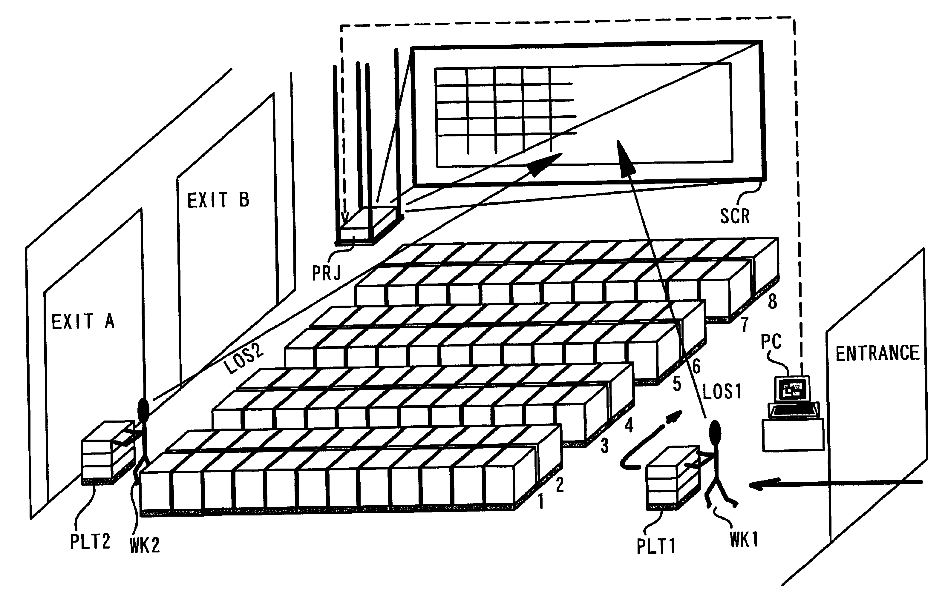
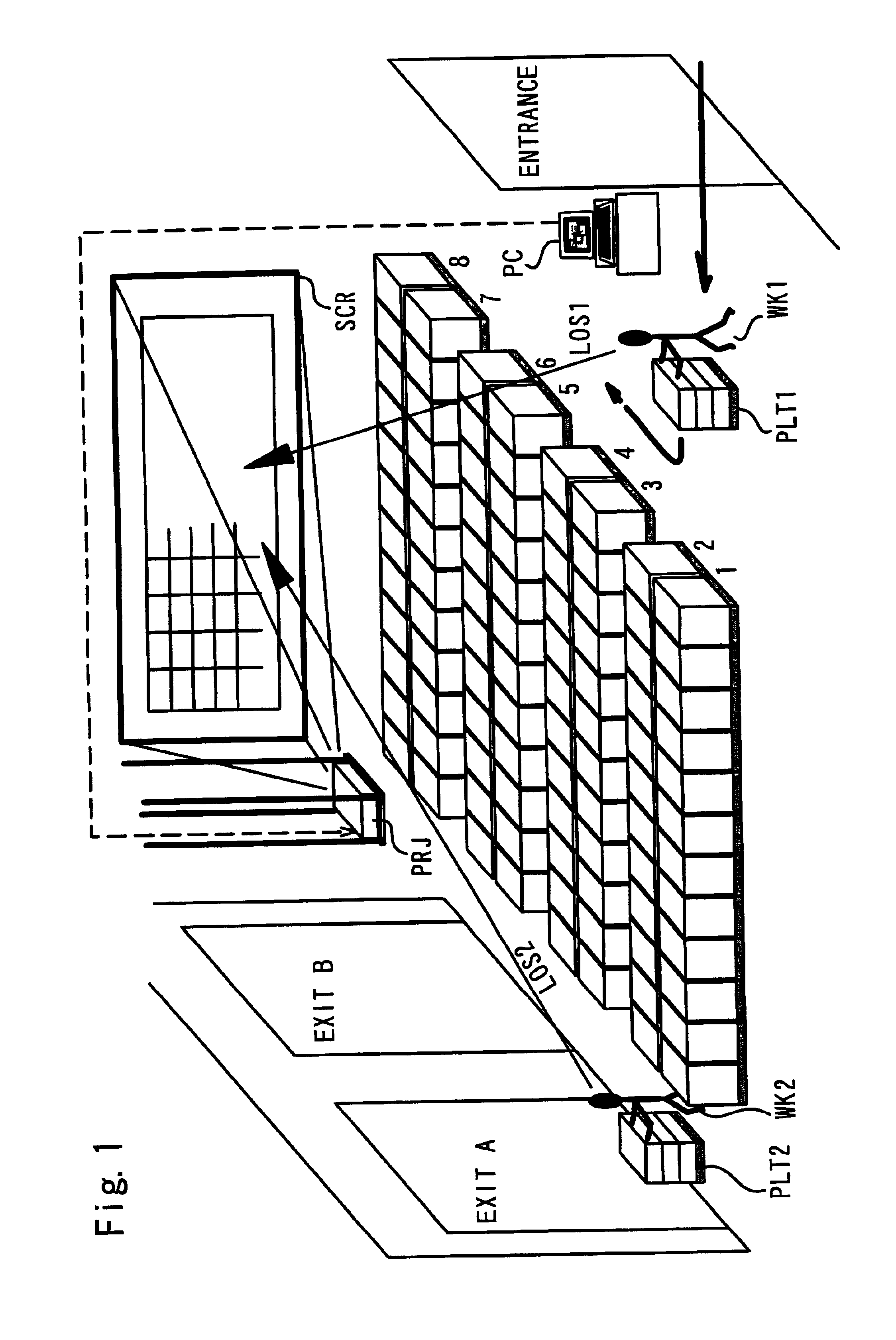
[0060]FIG. 1 illustrates the configuration of a management system in a first embodiment of the present invention. In this embodiment, the technique of the present invention is applied to a storehouse, which stores products manufactured in a factory. The technique is also applicable to a warehouse outside the factory.

[0061]A worker WK1 carries products mounted on a pallet PLT1 through an entrance into the storehouse. The worker WK1 locates the palette PLT1 in one of lanes 1 to 8 according to the type of the products as previously arranged. The lanes 1 to 8 respectively correspond to eight shipping containers. As for a certain lane where a planned number of the products is prepared, a worker WK2 carries out a palette PLT2 located in the certain lane through an exit A or an exit B. A motor truck with a container mounted thereon waits at each exit. The palette PLT2 is loaded on the container corresponding to the certain lane for shipment.

[0062]The management...

second embodiment

B. Application to Parts Distribution

[0083]FIG. 7 illustrates the configuration of a management system in a second embodiment of the present invention. This is a plan view of a factory. In the second embodiment, large display is applied for transmission of information between a parts warehouse A1 and an assembly area A2 in the factory.

[0084]The illustrated factory has two areas, that is, the parts warehouse A1 and the assembly area A2. These two areas are parted from each other across a passage, and it is difficult for each of the two areas to directly observe the status in the other area. The assembly area A2 includes a plurality of assembly lines L1, L2, . . . , and a specific model of products are produced in each assembly line. A distribution worker is present in the assembly area A1 to distribute the parts to each assembly line. The distribution worker monitors the degree of consumption of the respective parts and requires the parts warehouse A1 to deliver the parts when necess...

third embodiment

C. Application to Management Section

[0095]FIG. 9 illustrates the configuration of a management system in a third embodiment of the present invention. The layout of a factory is shown schematically. The third embodiment regards an application to transmission of information between a management section SR and production fields of the factory, that is, a parts warehouse A11, assembly lines A12, and a products warehouse A13.

[0096]In the production fields of the factory, parts are carried into the parts warehouse A11 and assembled to products in the assembly lines A12. The products are stored in the products warehouse A13 and are shipped when reaching a predetermined numerical quantity. The process of carrying the parts into the parts warehouse A11 is accordingly the specific upstream process in the production flow in the factory, and the shipment from the products warehouse A13 corresponds to the last process downstream most in the production flow. The assembly lines A12 correspond to ...


PUM


Abstract

The object of the present invention is to ensure information sharing in a factory and enhance the production efficiency.
The management system of the present invention utilizes a liquid crystal projector PRJ to project an image of management information on a large-scaled display in the factory. A screen SCR is located at a specific position that allows each worker to simultaneously recognize the display and the object of the display (for example, in the case of a storehouse, the storage status of products). The contents of the display are varied according to the location of the display: for example, (1) instructions and actual conditions of storage of products in the storehouse; and (2) requirement of parts from assembly lines to a parts warehouse and status of delivery of parts from the parts warehouse. In a staff room of managers, information with regard to a first process, which is upstream most in the work flow in the factory (status of carrying-in work of parts and materials from outside) and information with regard to a last process, which is downstream most in the work flow (status of shipment) are displayed simultaneously. Such display enables workers in various sections and managers to accurately grasp the working status in the factory in real time, thus attaining the smooth operations and enhancing the production efficiency.

Description

BACKGROUND OF THE INVENTION[0001]1. Field of the Invention[0002]The present invention relates to a management technique that manages working status in a factory and in a warehouse by utilizing a large-scaled display.[0003]2. Description of the Related Art[0004]In a factory or a warehouse, a large number of workers are generally scattered in a wide area for work. Accurate mutual transmission of information is essential to enhance the working efficiency under such conditions, the information including a work plan, actual working conditions, working instructions. It is desirable that the transmitted information has sufficient consistency, that the information is updated with a variation in working status without delay, and that a large number of workers share the information. One of the methods that satisfy these conditions is real-time display of the information using a large-scaled display connected to a computer.[0005]The position of the large-scaled display is conventionally determ...

Claims


Application Information

Patent Timeline
Patent Type & Authority Patents(United States)
IPC IPC(8): G05B15/02G05B19/418G06Q10/08G06Q50/00G06Q50/04G06Q50/28
CPCG05B15/02G06Q10/087G05B2219/31472G05B2219/31428
Inventor WATANABE, KAZUYOSHIOGUCHI, TAKASHIMARUYAMA, MITSUAKISHIMIZU, MAMORUICHIKAWA, TAKETOSHI
Owner SEIKO EPSON CORP
Why Eureka
Try Eureka