Flat ended double cube shaped tipped, screwdriver system

a screwdriver and cube shaped technology, applied in the direction of threaded fasteners, screws, fastening means, etc., can solve the problem of a user-friendly, secure grip screwdriver system, etc., to achieve convenient and efficient manufacturing and marketing, and low manufacturing cost. , the effect of durable and reliable construction

Inactive Publication Date: 2005-09-27
LEE HOWARD
View PDF8 Cites 30 Cited by
  • Summary
  • Abstract
  • Description
  • Claims
  • Application Information

AI Technical Summary

Benefits of technology

[0014]It is therefore an object of the present invention to provide a new and improved sure grip screwdriver system which has all of the advantages of the prior art tools of known designs and configurations and none of the disadvantages.
[0015]It is another object of the present invention to provide a new and improved sure grip screwdriver system which may be easily and efficiently manufactured and marketed.
[0016]It is further an object of the present invention to provide a new and improved sure grip screwdriver system which is of durable and reliable constructions.
[0017]An even further object of the present invention is to provide a new and improved sure grip screwdriver system which is susceptible of a low cost of manufacture with regard to both materials and labor, and which accordingly is then susceptible of low prices of sale to the consuming public, thereby making such sure grip screwdriver system economically available to the buying public.
[0018]Even still another object of the present invention is to provide a sure grip screwdriver system for allowing a user to screw and unscrew threaded fasteners in a convenient and efficient manner.

Problems solved by technology

While these devices fulfill their respective, particular objectives and requirements, the aforementioned patents do not describe a sure grip screwdriver system that allows a user to screw and unscrew threaded fasteners in a convenient and efficient manner.

Method used


Image

  • Flat ended double cube shaped tipped, screwdriver system
  • Flat ended double cube shaped tipped, screwdriver system
  • Flat ended double cube shaped tipped, screwdriver system

Examples


Embodiment Construction

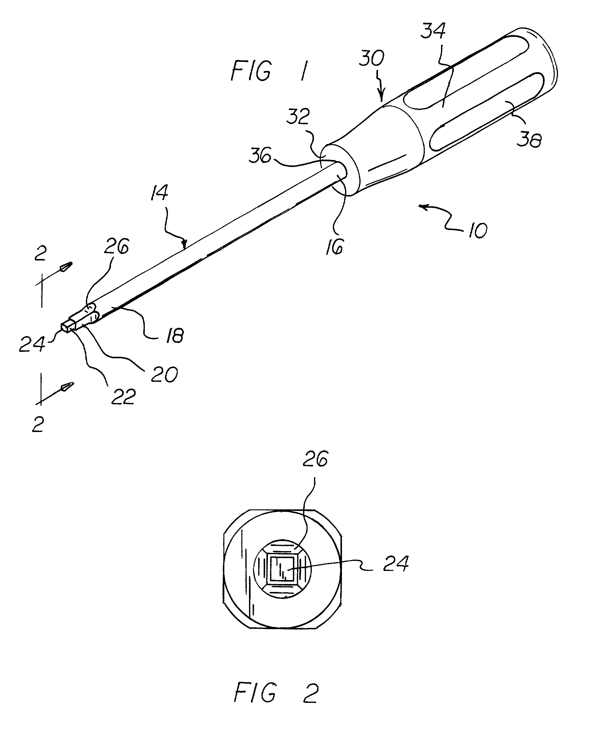
[0030]With reference now to the drawings, and in particular to FIG. 1 thereof, the preferred embodiment of the new and improved sure grip screwdriver system embodying the principles and concepts of the present invention and generally designated by the reference numeral 10 will be described.

[0031]The present invention, the screwdriver system 10 is comprised of a plurality of components. Such components in their broadest context include a shaft and a shaft support and a fastener. Such components are individually configured and correlated with respect to each other so as to attain the desired objective.

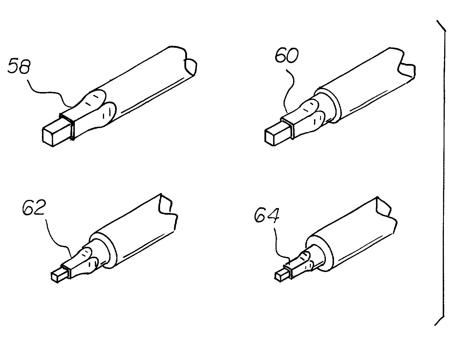
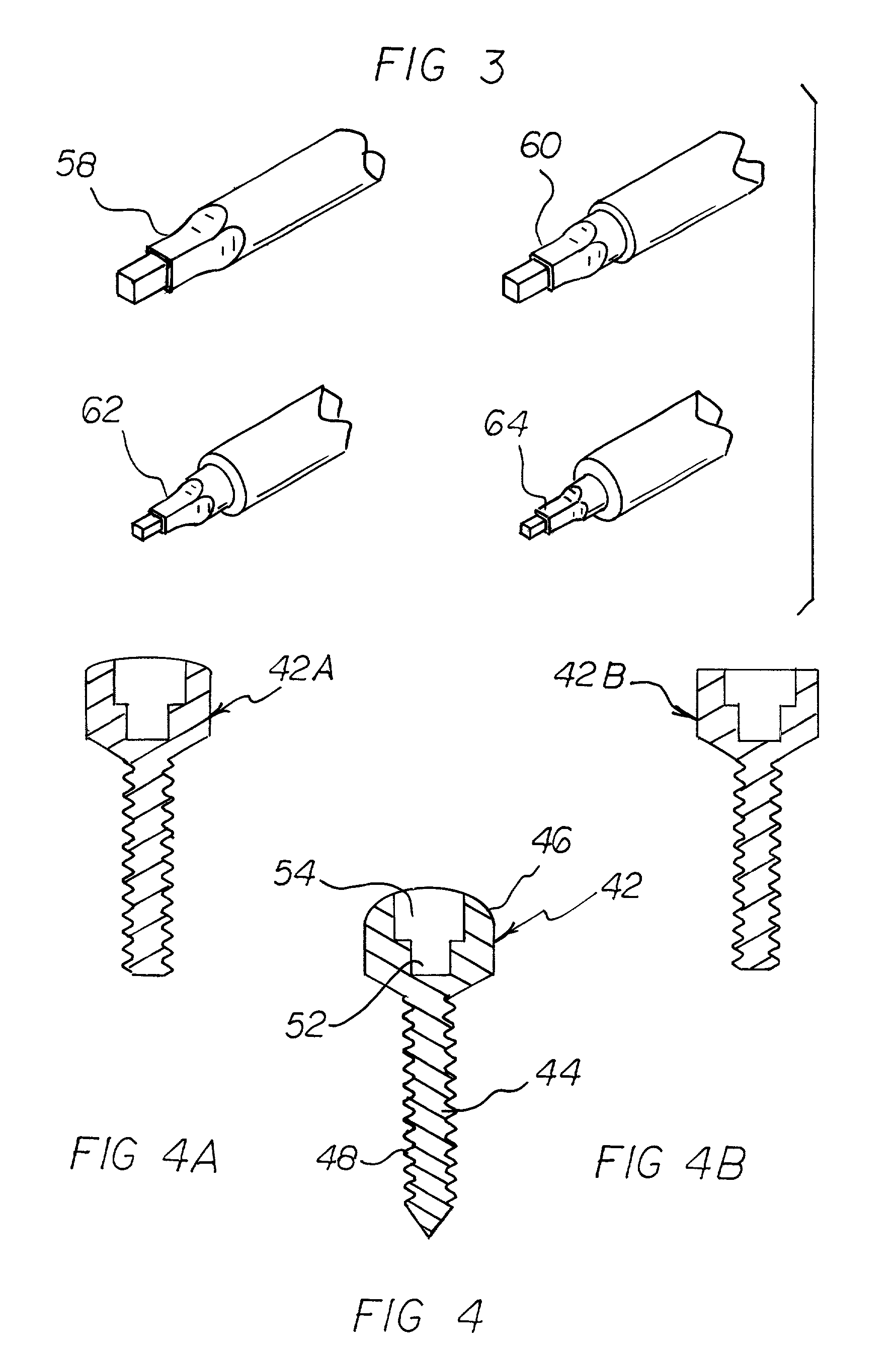
[0032]First provided is a shaft 14. The shaft is fabricated of a rigid metallic material. The shaft is in a cylindrical configuration with an axis. The shaft has a handle end 16 and a working end 18. The shaft has a working inner portion 20. The working inner portion is adjacent to the handle end. The shaft further has a working outer portion 22. The working outer portion is adjacent to ...


PUM


Abstract

A sure grip screwdriver system comprises a shaft. The shaft has a handle end and a working end. The shaft has a working inner portion and a working outer portion. The working inner portion is adjacent to the handle end. The working outer portion is adjacent to the working end. The working outer portion further has a generally cube-shaped configuration of a first smaller size. The working inner portion further has a generally cube-shaped configuration of a second larger size. Last provided is a shaft support. The shaft support has a recess at one end to receive the handle end of the shaft.

Description

BACKGROUND OF THE INVENTION[0001]1. Field of the Invention[0002]The present invention relates to a screwdriver system.[0003]2. Description of the Prior Art[0004]The use of tools of known designs and configurations is known in the prior art. More specifically, tools of known designs and configurations previously devised and utilized for the purpose of installing fasteners through known methods and apparatuses are known to consist basically of familiar, expected, and obvious structural configurations, notwithstanding the myriad of designs encompassed by the crowded prior art which has been developed for the fulfillment of countless objectives and requirements.[0005]By way of example, U.S. Pat. No. 3,640,175 discloses a ballistic shape screwhead and socket. U.S. Pat. No. 4,384,812 discloses a screw and screw forming tool. U.S. Pat. No. 4,911,593 discloses a ratchet driven threaded fastener U.S. Pat. No. 5,540,531 discloses a panel fastener. U.S. Pat. No. 5,460,064 discloses a universal...

Claims


Application Information

Patent Timeline
Patent Type & Authority Patents(United States)
IPC IPC(8): B25B15/00F16B23/00
CPCB25B15/008F16B23/0038
Inventor LEE, HOWARD
Owner LEE HOWARD
Why Eureka
Try Eureka