Scraper for animal stalls

Inactive Publication Date: 2005-09-27
BERG EQUIP CORP
View PDF21 Cites 12 Cited by
  • Summary
  • Abstract
  • Description
  • Claims
  • Application Information

AI Technical Summary

Benefits of technology

[0007]Alley scrapers of the present invention keep barn alleys clean. Clean alleys contribute to better animal health with fewer foot problems and a better overall barn environment. Clean alleys also provide safer conditions for both animals and workers with better footing. Clean alleys mean less animal stress, fewer muscle str

Problems solved by technology

With conventional blades, however, clean up efficiency is reduced by the fact that if a straight blade encounters an irregularity in the floor surface, a one piece blade is caused to rise up and thus leave areas which are not scraped clean.

Method used


Image

  • Scraper for animal stalls
  • Scraper for animal stalls
  • Scraper for animal stalls

Examples


Example

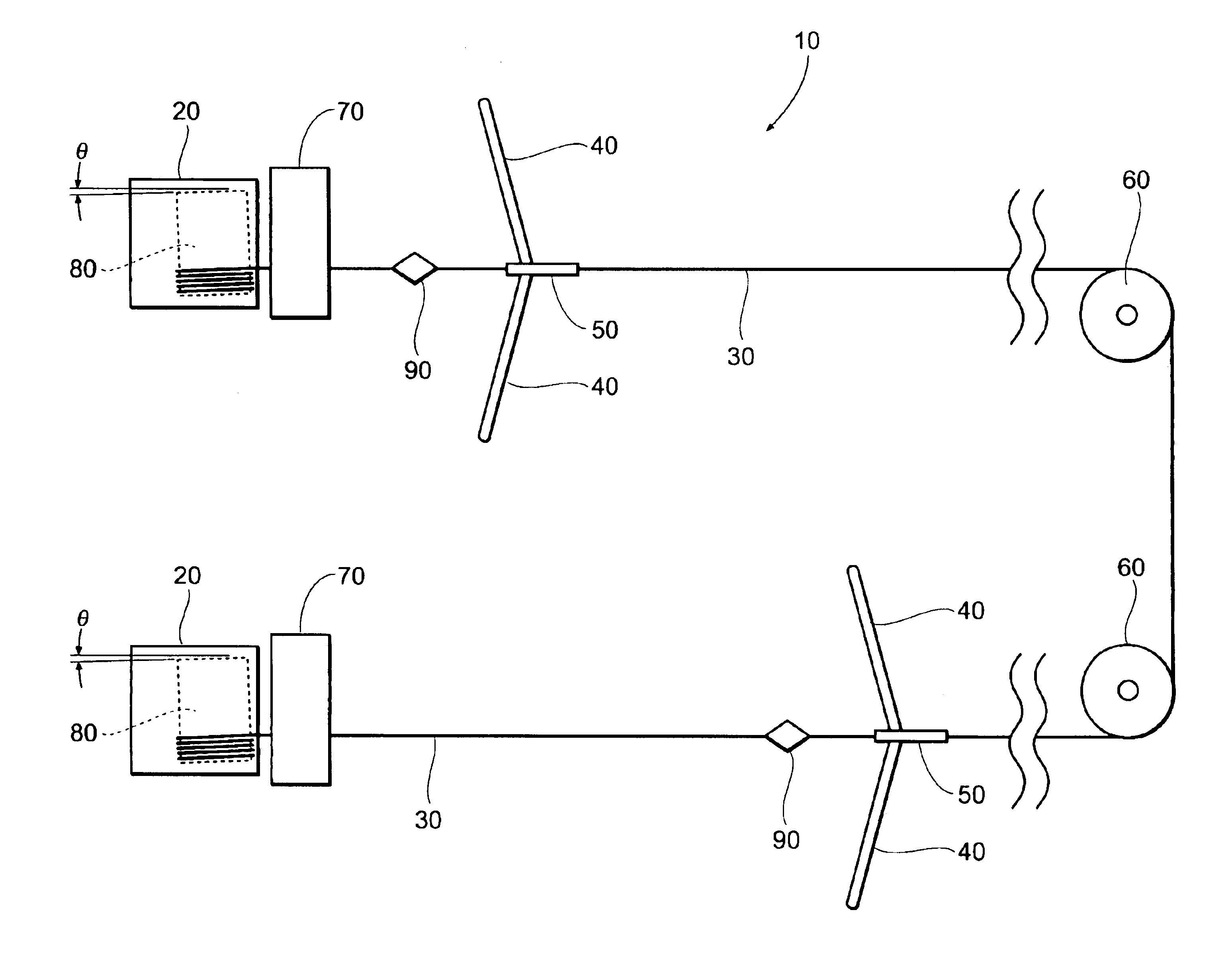
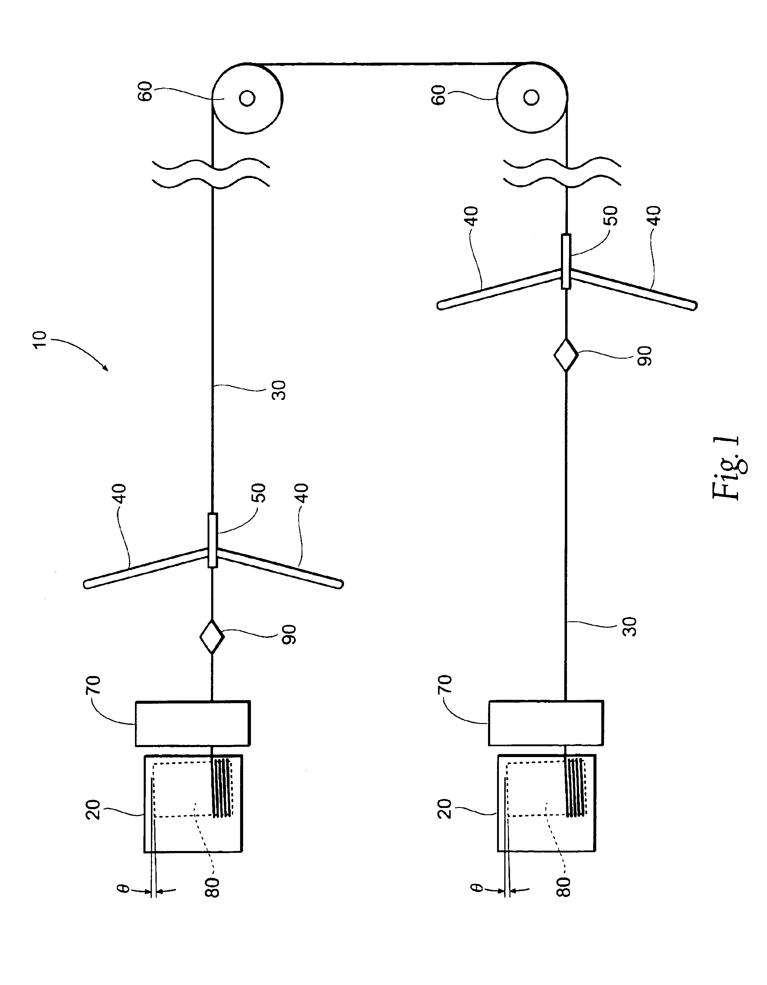
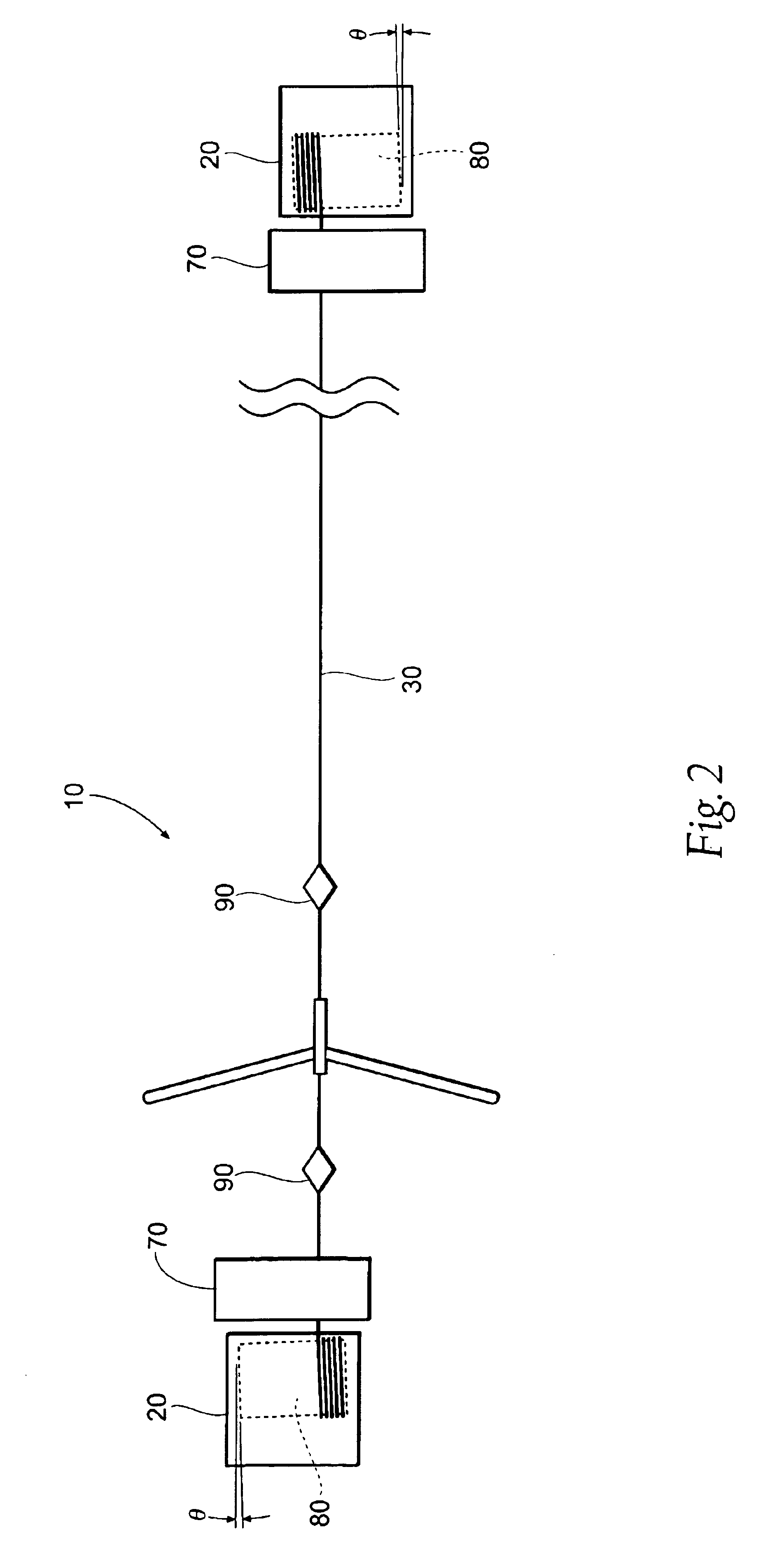
[0017]Referring to FIG. 1, there is seen a scraper assembly 10 of the present invention. Assembly 10 comprises first and second drum houses 20, a wire 30, a scraper 40, a draw bar 50, and wheels 60 if the user desires a multiple alley configuration.

[0018]The wire 30 runs between the two drum houses 20, around two wheels 60 in the displayed configuration, although more or less wheels 60 may be used in accordance with a desired configuration.

[0019]When one of the drums 80 within one of the drum housings 20 is operated in a forward direction (pulling cable) the second drum is allowed to operate in a reverse direction (feeding out cable) by disengaging a motor driving the reverse direction drum. Because of the gearing described later, the dead motor and drum will provide a sufficient drag on the scraper assembly 10 such that the cable 30 will be kept desirably taught.

[0020]In the preferred embodiment, two switch trippers 90 are provided closest in proximity to limit switch housings 70 r...


PUM

PropertyMeasurementUnit
Angleaaaaaaaaaa

Abstract

A scraper for removing debris from the floor of an animal stall is provided with a first motorized drum, a second motorized drum, a cable extending between the first and second drums, a scraper and a switch tripper carried by the cable. The switch tripper actuates a switch in communication with the first motorized drum to stop and reverse direction of the scraper and cable.

Description

RELATED APPLICATION[0001]This application claims the benefit of co-pending provisional Application Ser. No. 60 / 444,053, filed 31 Jan. 2003.[0002]This invention relates to equipment for animal husbandry. More specifically the invention relates to a scraper device particularly suited for clean up of cattle confinement areas such as barns, free stalls and pits.BACKGROUND OF THE INVENTION[0003]Various scraper devices have heretofore been utilized for the clean up of cattle stalls and barns. Typically such devices employ some type of scraper blade. With conventional blades, however, clean up efficiency is reduced by the fact that if a straight blade encounters an irregularity in the floor surface, a one piece blade is caused to rise up and thus leave areas which are not scraped clean.[0004]One type of scraper assembly is shown in U.S. Pat. No. 4,243,137 wherein a pair of scraper blades are hingedly connected to a frame. However, to allow the blades to move vertically the device of that p...

Claims


Application Information

Patent Timeline
IPC IPC(8): A01K1/01A47L11/00B65G25/04B65G25/08
CPCA01K1/0132B65G25/08
Inventor BERG, VERNON R.
Owner BERG EQUIP CORP
Why Eureka
Try Eureka