Device for regulating the flow of gas toward user equipment

a technology for regulating the flow of gas toward user equipment and equipment, applied in the direction of flow control, fluid pressure control, functional valve types, etc., can solve the problems of obvious damage, reduce waste, reduce gas significantly, and increase safety

Inactive Publication Date: 2005-09-27
CAVAGNA GROUP
View PDF7 Cites 8 Cited by
  • Summary
  • Abstract
  • Description
  • Claims
  • Application Information

AI Technical Summary

Benefits of technology

[0005]The aim of the invention is to solve the problem described above by providing a device for regulating the flow of gas toward user equipment, of the type with two regulation stages in succession, which in case of malfunction is capable of reducing significantly the amount of gas that is released, so as to achieve a considerable reduction of waste and an increase in safety.

Problems solved by technology

In current conditions, in case of malfunction the entire flow of gas is in practice dispersed, with obvious damage both as regards the economical aspect and as regards the occurrence of potential dangers.

Method used


Image

  • Device for regulating the flow of gas toward user equipment
  • Device for regulating the flow of gas toward user equipment
  • Device for regulating the flow of gas toward user equipment

Examples


Embodiment Construction

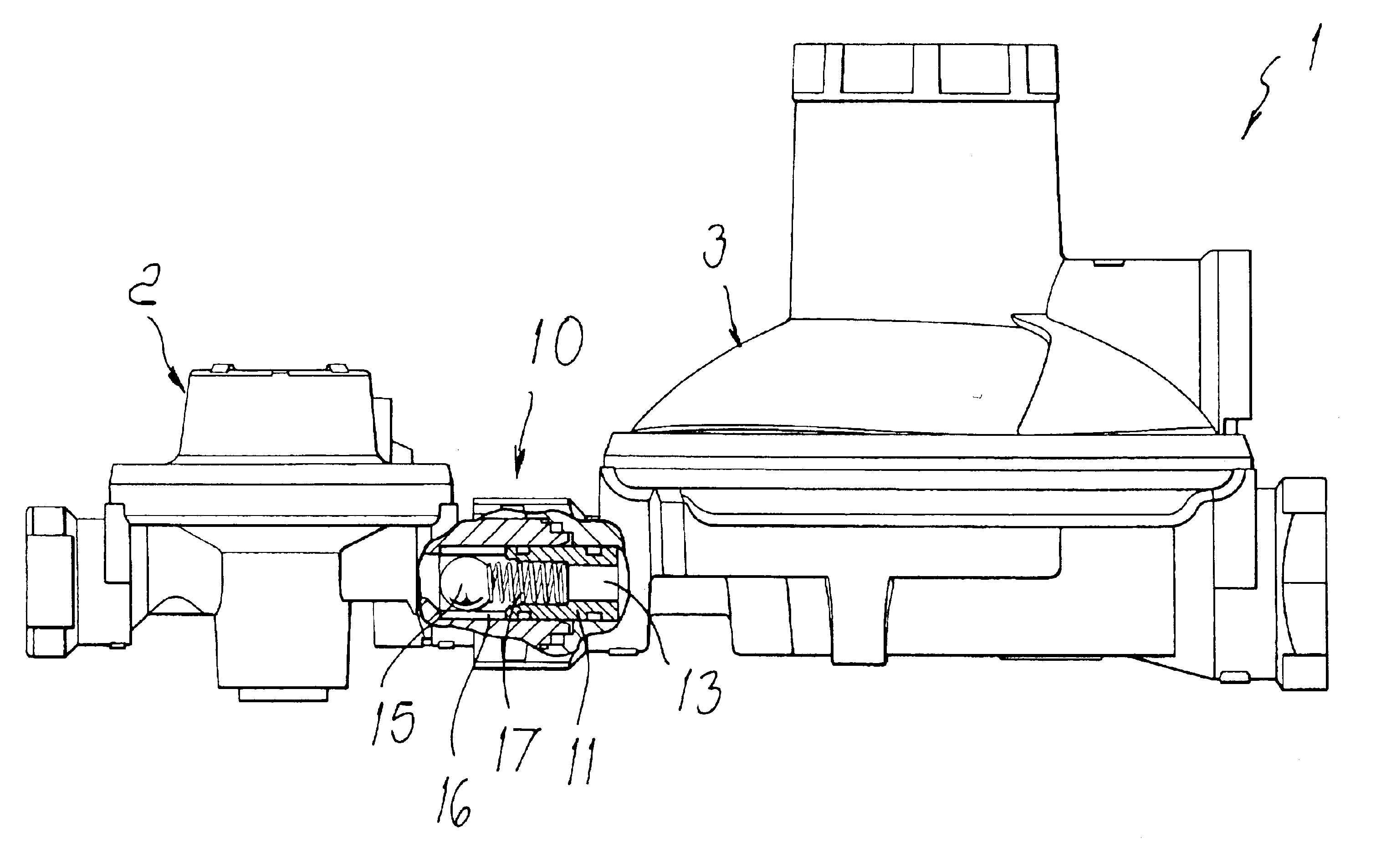
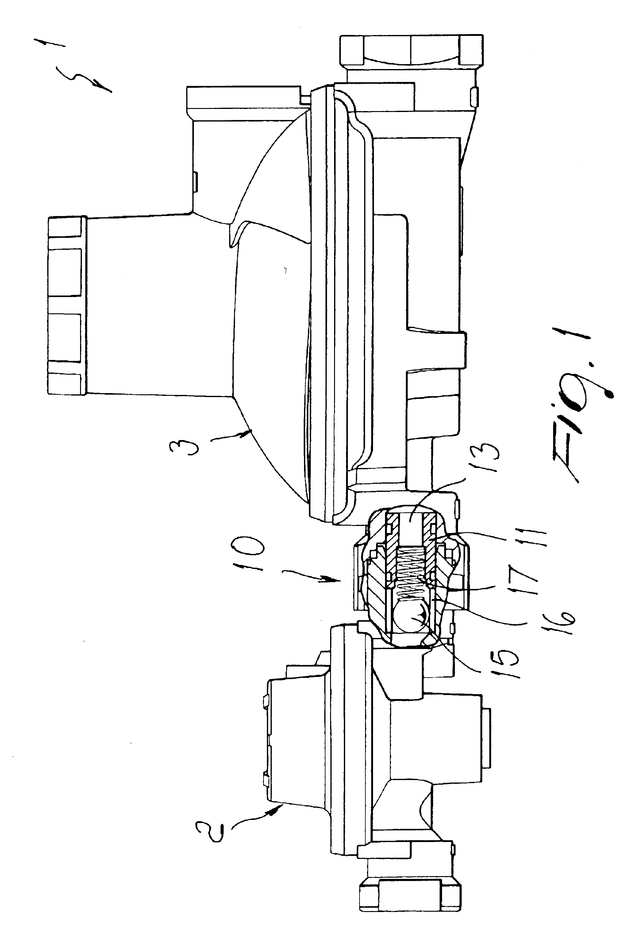
[0015]With reference to the figures, the device for regulating the flow of gas toward user equipment, generally designated by the reference numeral 1, comprises a first regulation stage 2, which is arranged externally, and a second regulation stage, designated by the reference numeral 3.

[0016]In the specific illustrated example, the first and second regulation stages are directly connected one another and arranged side by side; nothing changes conceptually if the first and second stages are physically spaced and connected by a connecting duct.

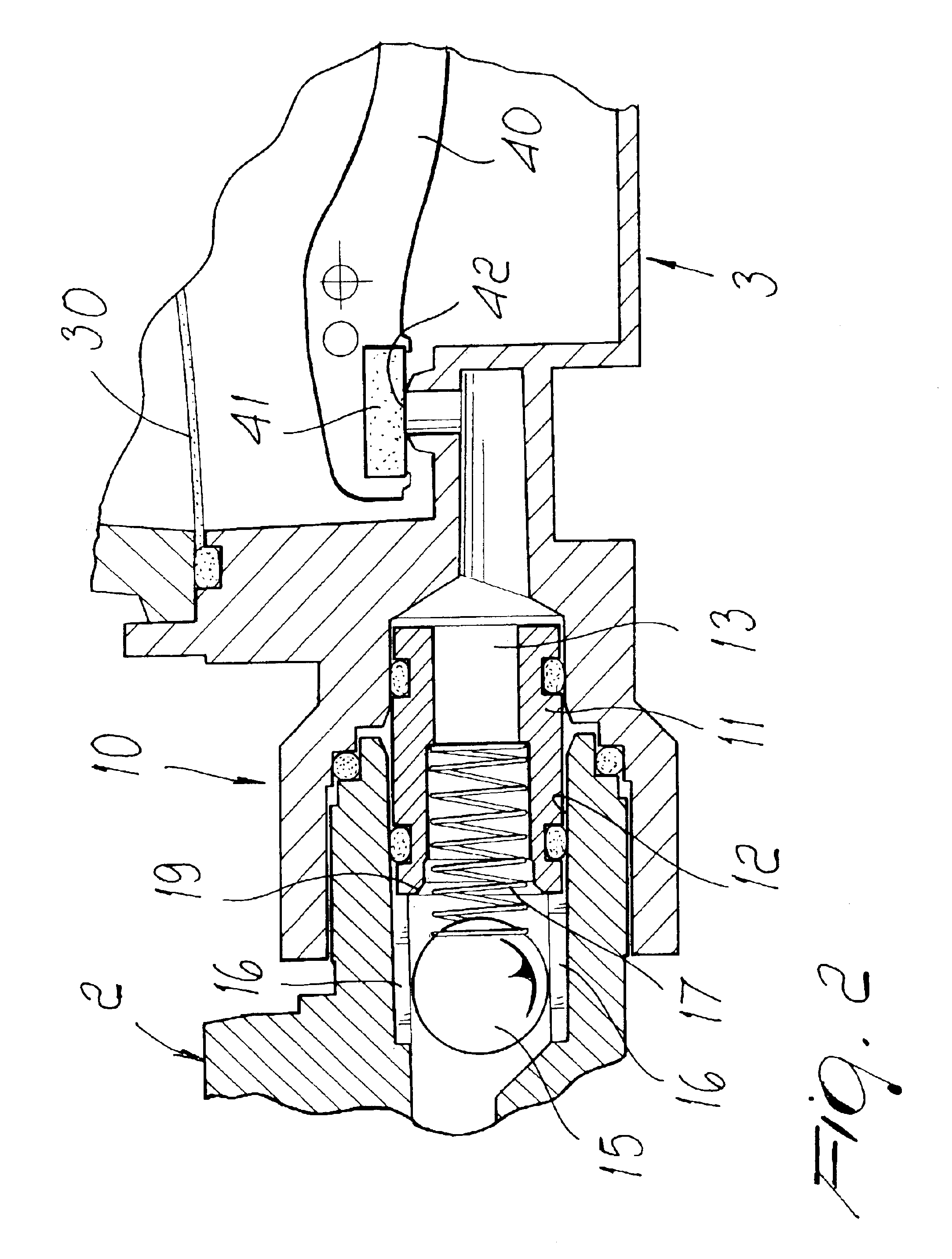
[0017]The particularity of the invention consists in that there is provided a flow limiter, generally designated by the reference numeral 10, which is interposed between the first stage 2 and the second stage 3 and is designed to act when a malfunction occurs in the second stage.

[0018]According to a preferred but not exclusive embodiment, the limiter 10 which is arranged at an outer casing 31 of the second stage, has a cylindrical bushing 11, w...


PUM


Abstract

A device for regulating a flow of gas toward user equipment, which comprises a first regulation stage and a second regulation stage arranged downstream in a direction of flow of the gas to be controlled, further comprising a flow limiter interposed between the first and second regulation stages and adapted to intervene if the second stage malfunctions.

Description

BACKGROUND OF THE INVENTION[0001]The present invention relates to a device for regulating the flow of gas toward user equipment.[0002]As is known, in order to regulate the pressure of the flow of gas toward user equipment, regulation devices have long been used which generally have a first regulation stage, normally located outside the building, downstream of which a second regulation stage is placed.[0003]With the current situation, in case of failure or malfunction of the second regulation stage, the gas is sent, by means of a venting valve, toward a discharge port that is different from the outlet port for connection to the user equipment.[0004]In current conditions, in case of malfunction the entire flow of gas is in practice dispersed, with obvious damage both as regards the economical aspect and as regards the occurrence of potential dangers.SUMMARY OF THE INVENTION[0005]The aim of the invention is to solve the problem described above by providing a device for regulating the f...

Claims


Application Information

Patent Timeline
Patent Type & Authority Patents(United States)
IPC IPC(8): F16K17/20F16K17/30G05D16/06G05D16/04G05D7/01G05D7/00
CPCF16K17/30G05D7/0106G05D16/0602G05D16/0402Y10T137/2607Y10T137/7794Y10T137/7795Y10T137/783Y10T137/7869
Inventor CAVAGNA, SAVIO
Owner CAVAGNA GROUP
Why Eureka
Try Eureka