Fuel injector

a fuel injector and injector technology, applied in the direction of fuel injection apparatus, fuel feed system, spraying apparatus, etc., can solve the problem of allowing very narrow tolerances, and achieve the effect of high axial deformation of the membran

Inactive Publication Date: 2005-09-27
ROBERT BOSCH GMBH
View PDF17 Cites 16 Cited by
  • Summary
  • Abstract
  • Description
  • Claims
  • Application Information

AI Technical Summary

Benefits of technology

[0008]In contrast, the fuel injector according to the present invention has the advantage over the related art that the moveable membrane makes it possible to achieve a reliable sealing of the actuator chamber from the fuel chamber. Furthermore it is advantageous that, because of the check valve, a rapid refilling of the pressure chamber takes place following the return of the piezoactuator to its original position and the return of the slave piston to its original position and the thus produced volume enlargement of the fuel chamber. The generated vacuum pressure opens the check valve and the hydraulic fluid rapidly continues to flow into the pressure chamber. The moveable membrane is advantageously able to be sealed in a durable manner if it is, for example, a thin metal membrane which may be affixed by welded seams both on the slave piston and also on the valve body of a fuel injector. The sealing lines themselves, thus, are no flexible sealing lines and are able to be permanently sealed for the lifetime. The required flexibility is provided solely by the elasticity of the membrane. In this context it is particularly advantageous that the membrane does not stand in the way of the mobility of the slave piston since the pressure prevailing in the actuator chamber and in the fuel chamber is the same, and the membrane, due to its deformability, moves into position in such a way that it itself need not absorb any forces arising from occurring pressure differences. Therefore, the piezoactuator is reliably protected from contact with the fuel and at the same time may be cooled by the highly viscous hydraulic fluid. It is also possible to protect it from wear caused by contact friction with the housing of the fuel injector.

Problems solved by technology

Thus, the use of deep-drawn parts able to be produced in a cost-effective manner from sheet metal, which do not allow any very narrow tolerances, is possible.

Method used


Image

  • Fuel injector
  • Fuel injector

Examples


Embodiment Construction

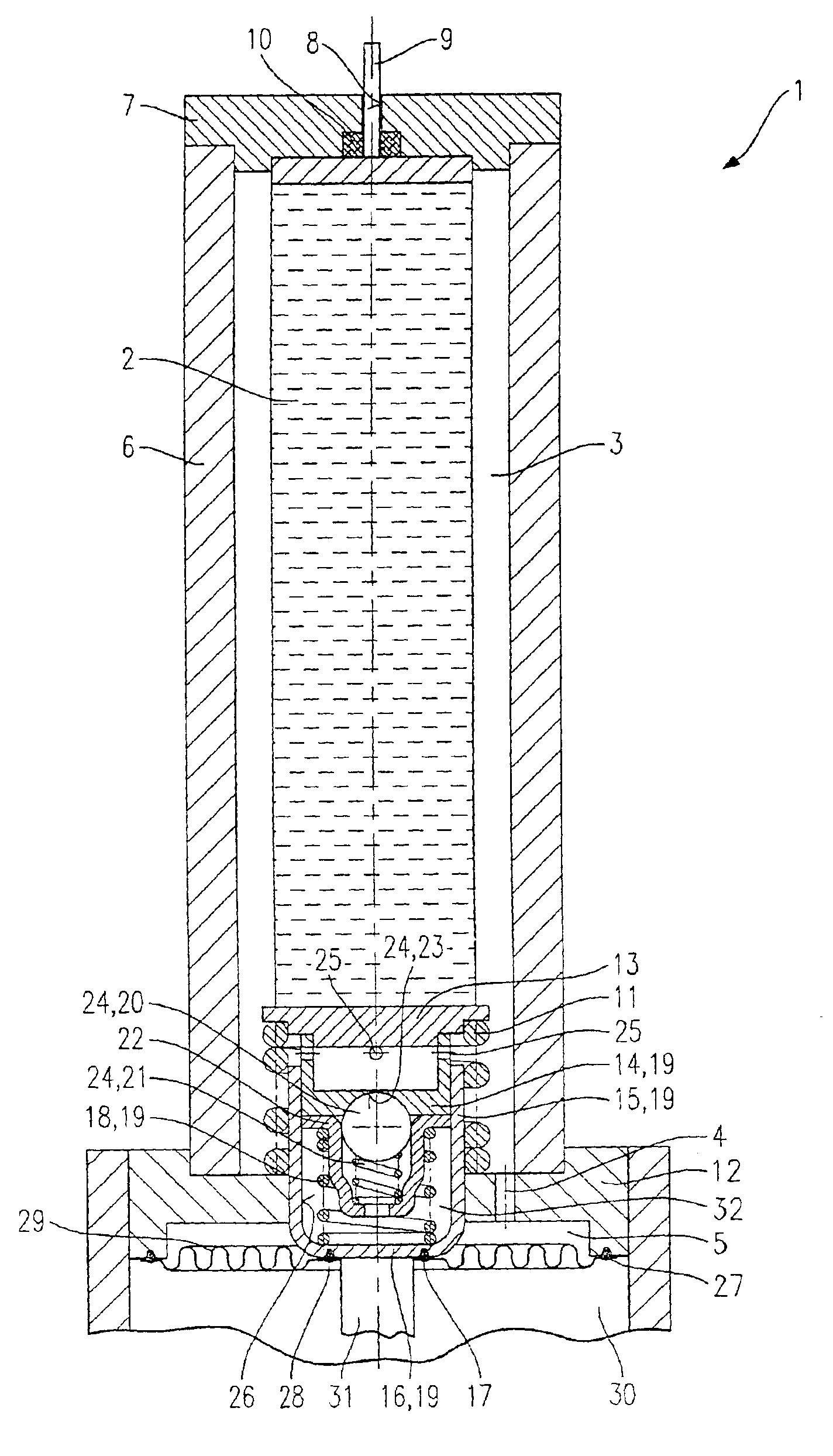
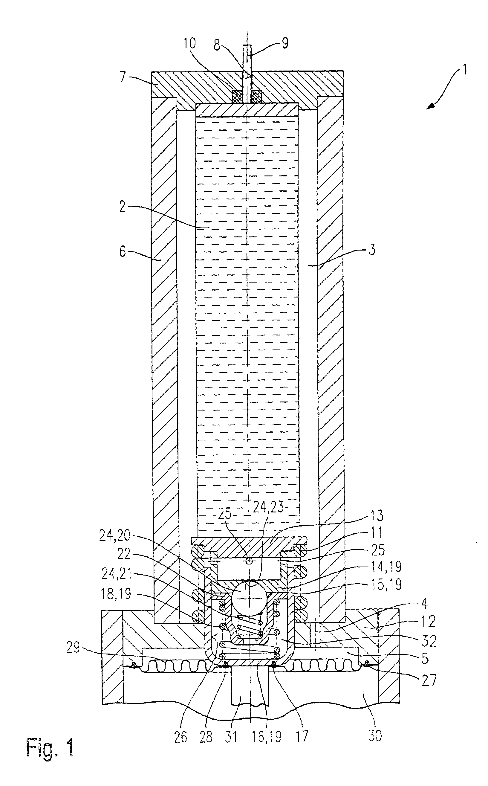
[0024]FIGURE schematically shows a cut-away portion of a fuel injector 1, an area of a piezoelectric or magnetostrictive actuator 2 being represented and an actuator chamber 3 which is connected to a lower actuator chamber 5 via a connecting bore 4. Actuator 2 is located in an actuator-chamber housing 6 which is bounded by a sealing plate 7. Electrical connections 9 are guided through a bore 8 in sealing plate 7 and sealed by an O-ring 10. Actuator 1 is activated by an electric voltage via these electrical connections 9. An actuator spring 11 is braced against an intermediate plate 12 and presses an actuator head 13 against actuator 2, so that actuator 2 comes to rest against sealing plate 7. Resting against actuator head 13 is a master piston 14 which is guided in a guide cylinder 15. Guide cylinder 15 is sealingly connected by a welded seam 17 to a slave piston 16 in a force-locking manner. A coupler spring 18 imparts an initial stress to master piston 14, which is intended to dri...


PUM


Abstract

A fuel injector, in particular a fuel injector for fuel-injection systems of internal combustion engines, having a piezoelectric or magnetostrictive actuator, has a coupler with a master piston and a slave piston which are connected to a pressure chamber. The pressure chamber is filled with an hydraulic fluid, and a coupler spring presses apart the master piston and the slave piston. The pressure chamber is connected to an actuator chamber via a check valve whose blocking direction faces the pressure chamber. The actuator chamber is sealed from a fuel chamber via a movable membrane.

Description

FIELD OF THE INVENTION[0001]The present invention is directed to a fuel injector.BACKGROUND INFORMATION[0002]European Published Patent Application No. 0 477 400 describes an hydraulic coupler for a piezoelectric actuator in which the actuator transmits a lifting force to a master piston. The master piston is in force-locking connection to a guide cylinder for a slave piston. The slave piston, the guide cylinder and the master piston sealing the guide cylinder form an hydraulic chamber. A spring which presses apart the master piston and the slave piston is situated in the hydraulic chamber. Arranged around an end section of the guide cylinder and the slave piston is a rubber sleeve which seals a holding chamber for a viscous hydraulic fluid from a fuel chamber. The viscosity of the hydraulic fluid is adapted to the ring gap between the slave piston and the guide cylinder.[0003]The slave piston mechanically transmits a lifting movement to a valve needle, for instance. In response to t...

Claims


Application Information

Patent Timeline
Patent Type & Authority Patents(United States)
IPC IPC(8): F02M61/00F02M61/08F02M51/06F02M51/00
CPCF02M51/0603F02M61/08F02M2200/21
Inventor EICHENDORF, ANDREAS
Owner ROBERT BOSCH GMBH
Why Eureka
Try Eureka