Sensor system for buried waste containment sites

a waste containment site and sensor technology, applied in the field of sensor systems, can solve the problems of difficult to provide a barrier of consistent strength, difficult to maintain balance, and expensive methods, and achieve the effect of improving safety and avoiding accidents

Inactive Publication Date: 2005-09-27
BATTELLE ENERGY ALLIANCE LLC
View PDF32 Cites 5 Cited by
  • Summary
  • Abstract
  • Description
  • Claims
  • Application Information

AI Technical Summary

Benefits of technology

[0022]In accordance with another aspect of the invention, one or more access tubes are disposed in or below the barriers with at least one end of the tubes extending from the barriers to allow access thereinto. Sensor devices are then disposed in the access tube or tubes and coupled to the signal processing device through the one end of the tubes. The access tubes provide protection for the sensor device without inhibiting operation thereof. Also, use of access tubes allows for selective removal and deployment of a variety of sensors.

Problems solved by technology

However, such method is costly, impractical, and dangerous.
Digging up sites with buried drums, radioactive dusts, or other airborne wastes may actually release the contaminants, spreading them into the atmosphere and through the soil.
The above-described system has a number of shortcomings, including the possibility of further spreading contaminants by the use of hydraulic jets, the difficulty of maintaining balance between the amount of slurry needed for cutting and the amount of slurry needed for hardening the soil, the difficulty of providing a barrier of consistent strength since it would depend in part upon the soil composition encountered and the amount of slurry deposited, and, finally, the lack of testing of excavated soil to know whether soil surrounding the waste site has become contaminated.

Method used


Image

  • Sensor system for buried waste containment sites
  • Sensor system for buried waste containment sites
  • Sensor system for buried waste containment sites

Examples


Embodiment Construction

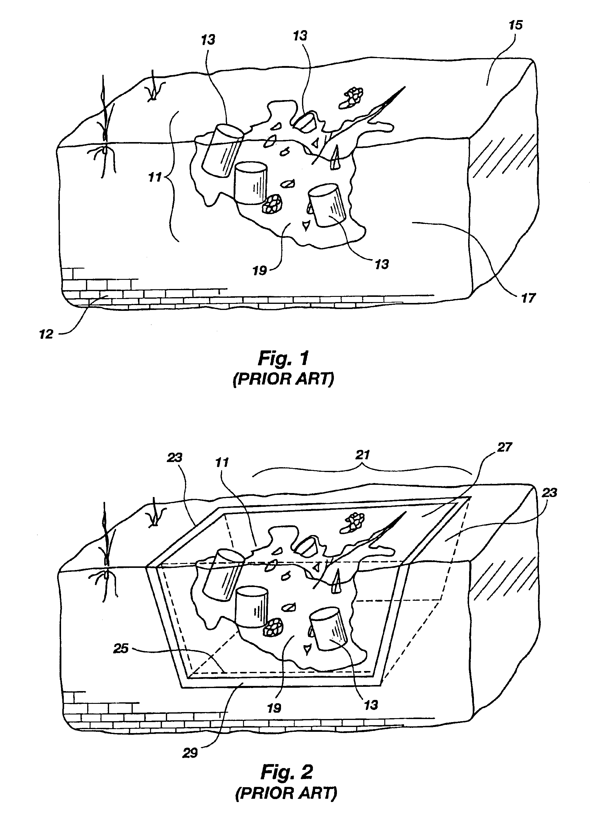
[0037]Referring now to FIG. 1, a typical waste site 11 is shown containing drums 13 filled with hazardous waste, both on the surface 15 and buried under the ground 17. Contaminants 19, leaking from the drums 13, threaten to migrate into a water table 12, unless some type of containment barrier can be provided.

[0038]One such containment barrier 21 is shown in FIG. 2 to include side barriers or walls 23 and a floor or horizontal barrier 29. The side barriers 23 may be made using conventional methods and interconnected to the horizontal barrier 29. Additionally, the waste site 11 could be completely encapsulated by forming an upper barrier cover (not shown) and interconnecting it with the side barriers 23 and front and rear barriers 25 and 27 (front barriers 25 are shown in phantom line in FIG. 2). The afore-cited co-pending patent application describes how containment barriers of the type described may be constructed using apparatus such as that to next be briefly described.
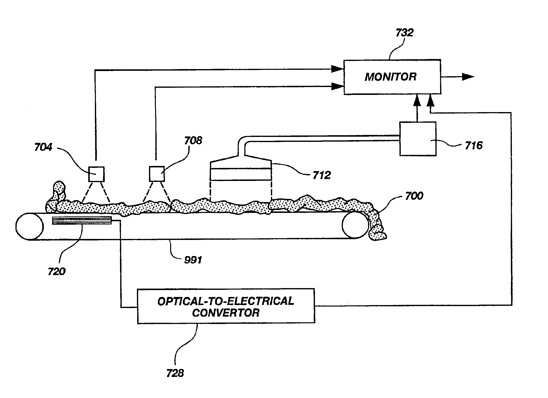
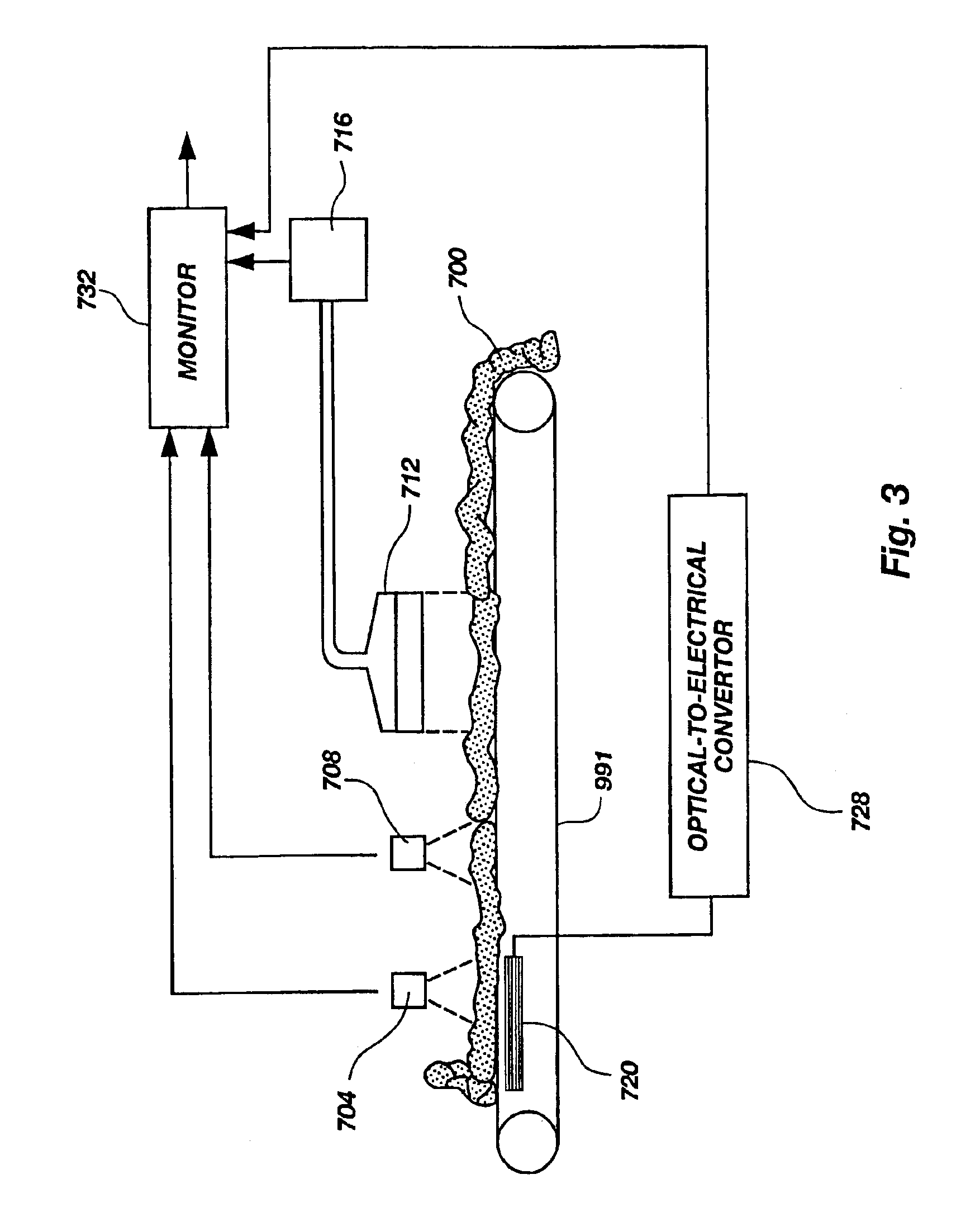
[0039]FIG....


PUM


Abstract

A sensor system for a buried waste containment site having a bottom wall barrier and / or sidewall barriers, for containing hazardous waste. The sensor system includes one or more sensor devices disposed in one or more of the barriers for detecting a physical parameter either of the barrier itself or of the physical condition of the surrounding soils and buried waste, and for producing a signal representing the physical parameter detected. Also included is a signal processor for receiving signals produced by the sensor device and for developing information identifying the physical parameter detected, either for sounding an alarm, displaying a graphic representation of a physical parameter detected on a viewing screen and / or a hard copy printout. The sensor devices may be deployed in or adjacent the barriers at the same time the barriers are deployed and may be adapted to detect strain or cracking in the barriers, leakage of radiation through the barriers, the presence and leaking through the barriers of volatile organic compounds, or similar physical conditions.

Description

RELATED APPLICATION[0001]This application is a Divisional of allowed U.S. application Ser. No. 09 / 418,681, filed on Oct. 14, 1999 now U.S. Pat. No. 6,648,552.CONTRACTUAL ORIGIN OF THE INVENTION[0002]The United States Government has certain rights in this invention pursuant to Contract No. DE-AC07-94ID13223, DE-AC07-99ID13727, and Contract No. DE-AC07-05ID14517 between the United States Department of Energy and Battella Energy Alliance, LLC.BACKGROUND OF THE INVENTION[0003]1. Field of the Invention[0004]The present invention relates generally to a sensor system for monitoring the structural integrity of an underground waste containment barrier, and leakage therefrom of waste products or byproducts, and for improved characterization of zones of interest.[0005]2. Background Art[0006]It is often necessary to form a containment barrier around a hazardous waste site to stop or prevent the migration of contaminants into the nearby soil and water tables. The containment barrier must prevent...

Claims


Application Information

Patent Timeline
Patent Type & Authority Patents(United States)
IPC IPC(8): G21F9/34G21F5/00
CPCB09B1/00E02D31/004G01M3/047G01M3/165G01M3/38G01M3/40G21F9/34E02F5/145
Inventor SMITH, ANN MARIEGARDNER, BRADLEY M.KOSTELNIK, KEVIN M.PARTIN, JUDY K.LANCASTER, GREGORY D.PFEIFER, MARY CATHERINE
Owner BATTELLE ENERGY ALLIANCE LLC
Why Eureka
Try Eureka