Lift mechanism for plunge routers

a technology of plunge router and mechanism, which is applied in the field of plunge router, can solve the problems of difficult and awkward adjustment of router bit height, complicated structure of mechanism, and high manufacturing cost, and achieve the effect of convenient operation and efficient operation

Inactive Publication Date: 2005-09-27
WOODPECKERS LLC
View PDF16 Cites 32 Cited by
  • Summary
  • Abstract
  • Description
  • Claims
  • Application Information

AI Technical Summary

Benefits of technology

[0004]In accordance with the present invention, an improved lift mechanism is provided for adjusting the router bit height of a plunge router relative to the working surface of a router table beneath which the plunge router is mounted. More particularly in this respect, the lift mechanism is operable from the top side of the router table, thereby eliminating any awkwardness with regard to making a desired adjustment and minimizing the effort required to achieve adjustment. Still further in accordance with the invention, the upper end of the lift mechanism can be provided with indicia visible at the top side of the table, thus promoting precision and accuracy with respect to adjustments of the router bit height relative to the top side of the table. A lift mechanism according to the invention comprises a threaded lift rod rotatable relative to the router table and a lift arm threadedly interengaged with the rod and having an end radially spaced from the rod and attached to the router, whereby rotation of the lift rod results in axial displacement of the lift arm and thus the router relative to the table. Accordingly, it will be appreciated that a lift mechanism according to the invention comprises a minimum number of component parts which are structurally interrelated in a manner which makes the operation thereof and thus the desired adjustment of a plunge router relative to a router table extremely efficient and easy to achieve while, at the same time, providing for incremental adjustment and the ability to optimize accuracy with respect to a given adjustment.
[0005]It is accordingly an outstanding object of the present invention to provide an improved lift mechanism for adjusting the height of a plunge router bit relative to a router table beneath which the plunge router is mounted.
[0007]A further object is the provision of a lift mechanism of the foregoing character which is structurally simple, easy to operate and efficient in operation.
[0008]Yet another object is the provision of a lift mechanism of the foregoing character by which the height of a router bit relative to the router table can be incrementally adjusted with accuracy.

Problems solved by technology

When so mounted, however, it becomes very difficult and awkward to adjust the router bit height in that the latter adjustment must be made from under the table.
While this arrangement may decrease the awkwardness and difficulty of adjusting the router bit height relative to the table, the mechanism is structurally complex and expensive to manufacture and still requires manipulating the adjusting components from beneath the table.

Method used


Image

  • Lift mechanism for plunge routers
  • Lift mechanism for plunge routers
  • Lift mechanism for plunge routers

Examples


Embodiment Construction

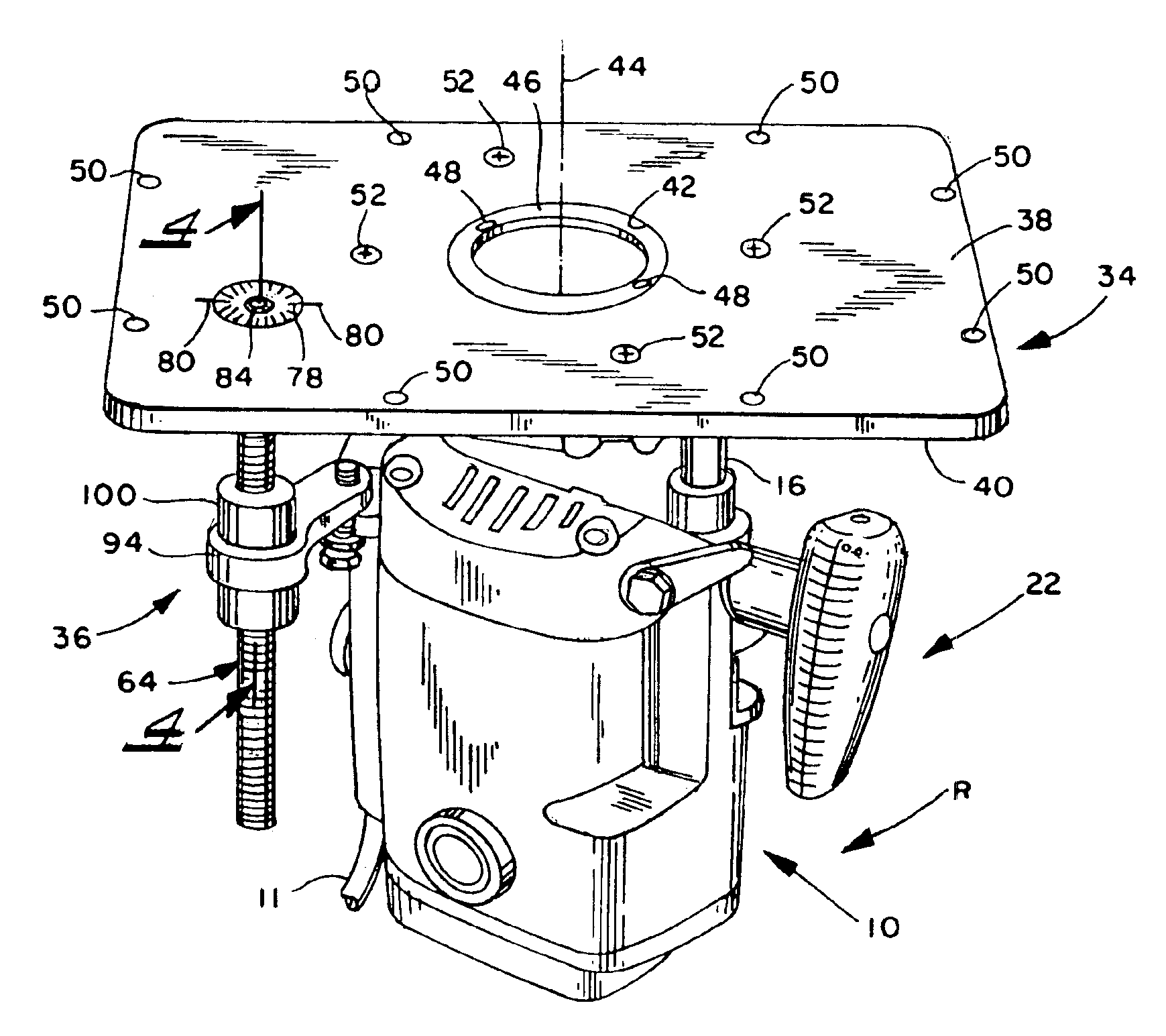
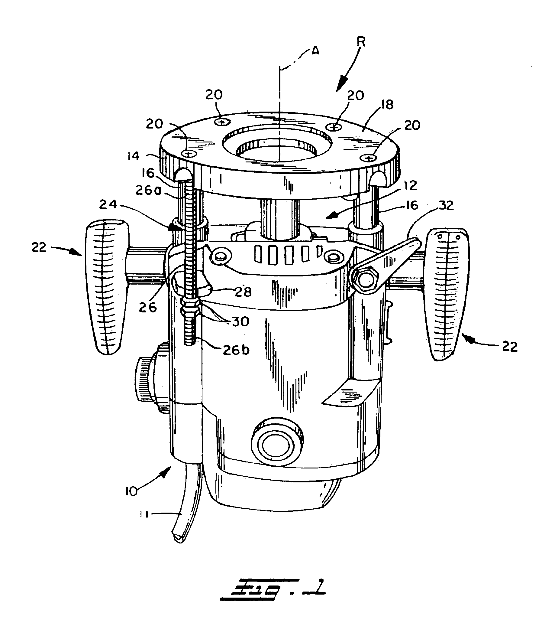
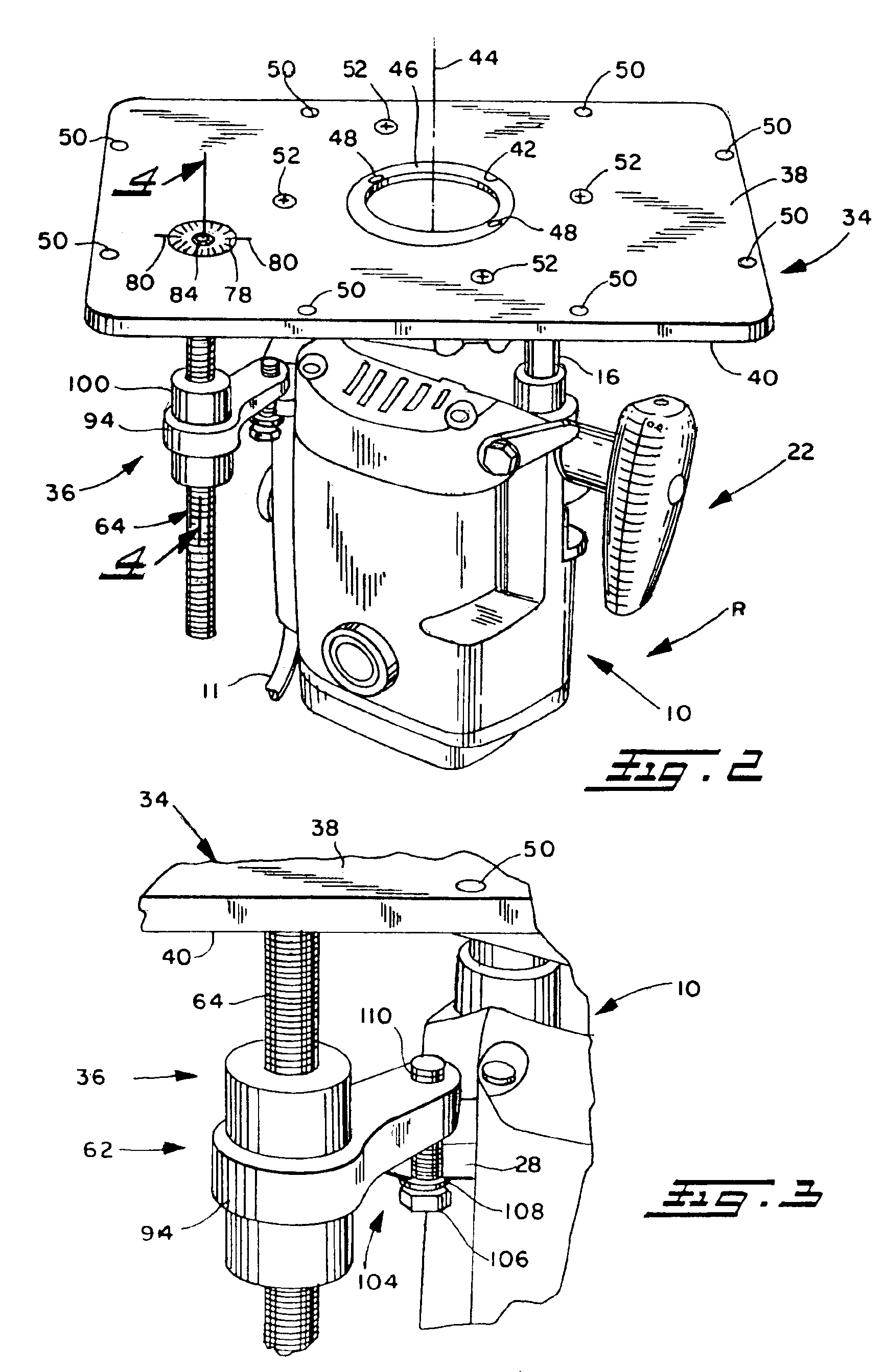
[0015]Referring now in greater detail to the drawings, wherein the showings are for the purpose of illustrating a preferred embodiment of the invention only, and not for the purpose of limiting the invention, FIG. 1 of the drawing illustrates a Hitachi Model M12V plunge router R and is shown only to provide an example of the type of router to which the present invention is applicable. As is well known, routers of the character shown in FIG. 1 are electric motor driven and include a housing 10 enclosing the electric motor which has a power cord 11 and an output shaft provided with a router bit chuck 12 for removably mounting a desired router bit on the router for rotation about the router axis A. The router further includes a base 14 mounted on the axially outer ends of a pair of support and guide rods 16 which are axially slidably received in bores provided therefor in the housing, whereby the base is axially displaceable toward and away from housing 10. While not shown, it is well ...


PUM

PropertyMeasurementUnit
axial displacementaaaaaaaaaa
axial thicknessaaaaaaaaaa
axial lengthaaaaaaaaaa

Abstract

A lift mechanism for a plunge router mounted on the underside of a router table comprises an adjusting screw extending vertically beneath the table and being rotatable relative to the table from the top side thereof, and a lift arm threadedly engaged with the screw and having an end spaced from the screw and interconnected with the router, whereby rotation of the screw displaces the router relative to the table.

Description

BACKGROUND OF THE INVENTION[0001]This invention relates to the art of routers and, more particularly, to an improved lift mechanism for adjusting the position of a plunge router relative to the work supporting surface beneath which the router is mounted.[0002]It is of course well known that a plunge router comprises a router base transverse to and axially slidably interengaged with the router housing for adjusting the axial distance between the router and base and thus the position of a router bit relative to the base. The base is axially slidably interengaged with the router housing by a pair of guide rods attached to the base and extending into guide rod receiving passages in the router housing, and spring components bias the guide rods and thus the router base axially outwardly of the router housing. An adjustable stop rod mechanism provides for adjusting the axial position of the base relative to the router housing and thus the plunge depth of the router bit.[0003]It is also wel...

Claims


Application Information

Patent Timeline
Patent Type & Authority Patents(United States)
IPC IPC(8): B27C5/10B27C9/02
CPCB27C5/10B27C9/02Y10T409/306608Y10T409/30924
Inventor HUMMEL, RICHARD M.
Owner WOODPECKERS LLC
Why Eureka
Try Eureka