Closing device in an injection moulding machine for plastics

a technology of injection molding machine and closing device, which is applied in the field of plastics sealing device in injection molding machine, can solve the problem of occupying a relative large space of the sealing device, and achieve the effect of shortening the length and cost-effective construction

Inactive Publication Date: 2005-09-27
MANNESMANN PLASTICS MACHINERY
View PDF7 Cites 6 Cited by
  • Summary
  • Abstract
  • Description
  • Claims
  • Application Information

AI Technical Summary

Problems solved by technology

This embodiment has also the drawback that the clamping device demands a relative large space because the spindle juts out considerably from the backside of the end platen, when the clamping unit is open.

Method used


Image

  • Closing device in an injection moulding machine for plastics
  • Closing device in an injection moulding machine for plastics
  • Closing device in an injection moulding machine for plastics

Examples


Embodiment Construction

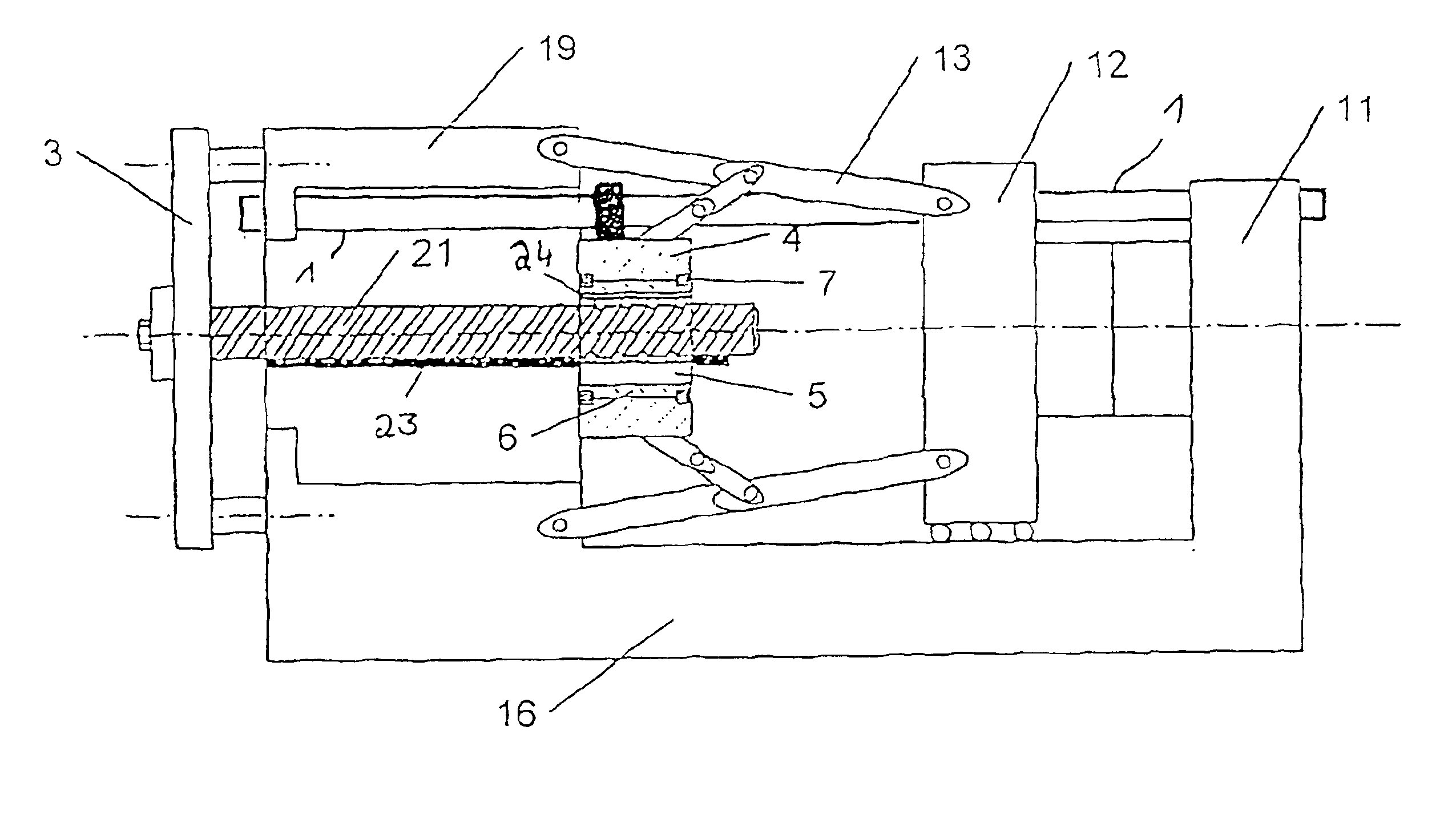
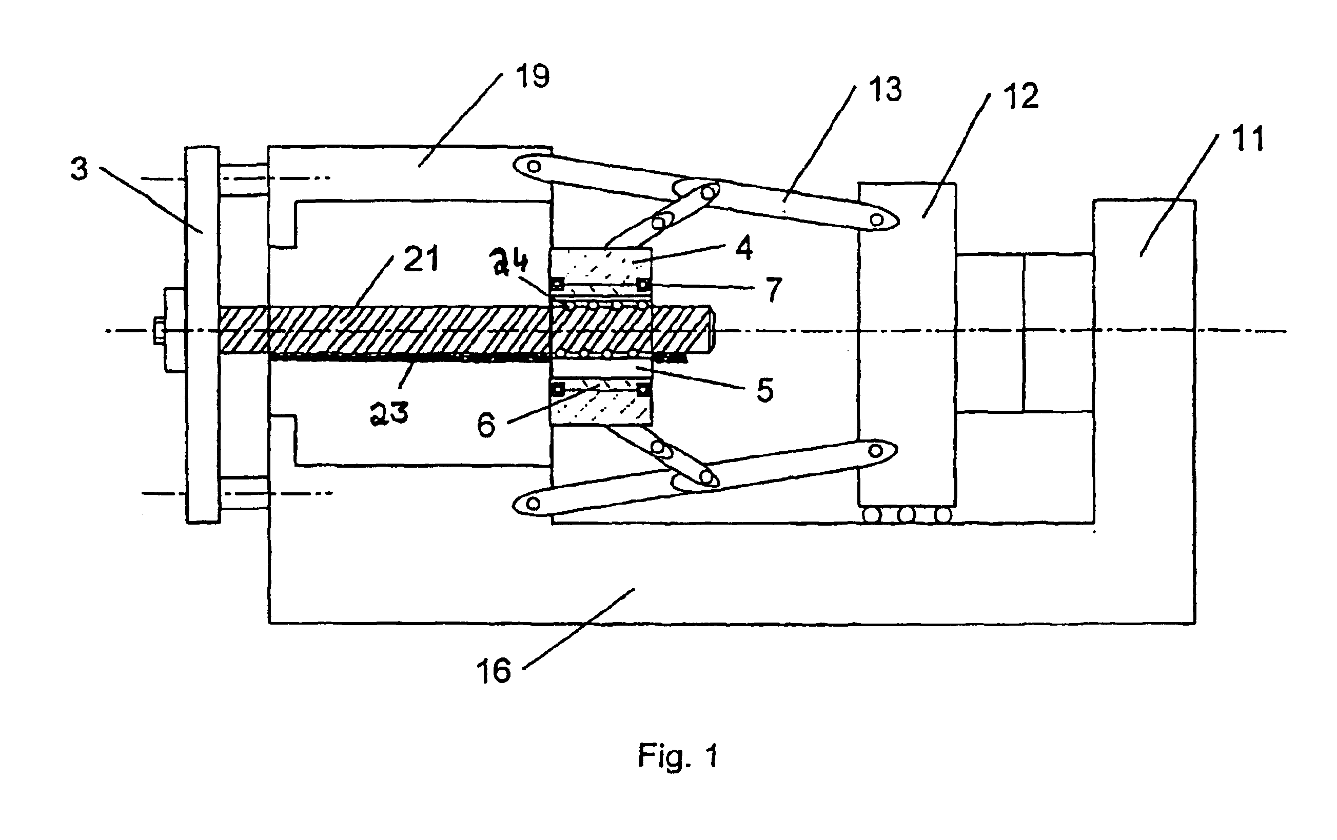
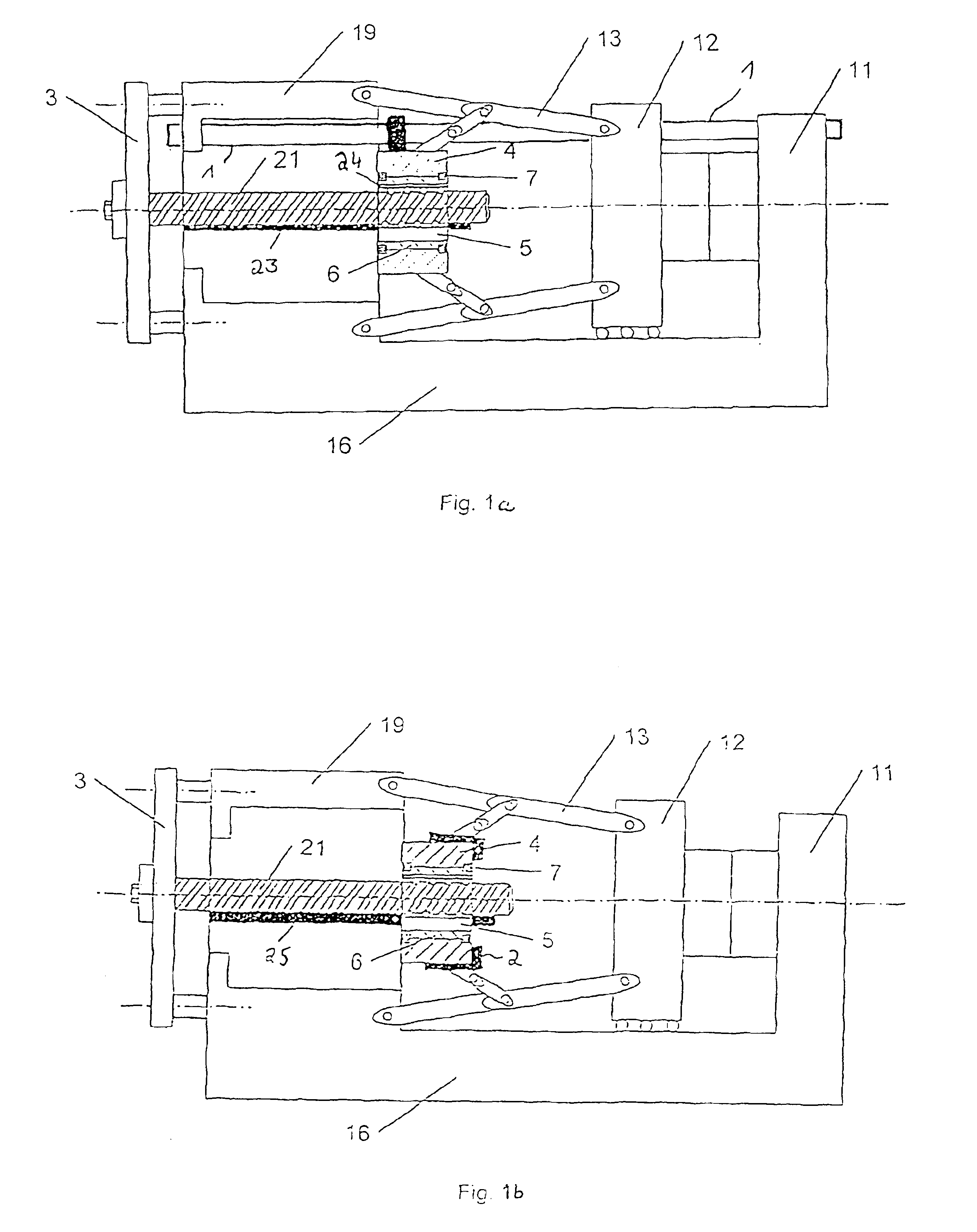
[0011]An example of the invention is illustrated in the attached FIG. 1. Arranged on a machine bed 16 is a fixed platen 11, whereby a moveable platen 12 is able to move axially relative to the fixed platen by a toggle mechanism 13. The moving platen 12 is movably guided on several tie bars 1, as shown in FIG. 1a (only one is shown here), which extend in a manner known per se between the fixed platen and an end plate 19, whereby the fixed platen 11 is connected via the machine bed 16 with the end platen 19. A spindle 21 is guided with its end distal to the moving platen through the end platen 19 and connected in a rotationally fixed manner in an anchor plate 3. Flange-mounted to the toggle mechanism 13 on the other end of the spindle 21 is a hollow-shaft motor 7. A spindle nut 5 is coupled with the hollow shaft or the rotor 6 of the hollow-shaft motor and is in engagement with the spindle 21. In the presently illustrated example, the stator 4 of the hollow-shaft motor is flange-mount...


PUM

PropertyMeasurementUnit
lengthaaaaaaaaaa
forceaaaaaaaaaa

Abstract

The invention relates to a clamping device for an injection molding machine for plastics, including a fixed platen (11) which is connected to a moving platen (12) by means of a toggle mechanism (13). A hollow-shaft motor (7) is provided to cooperate with a spindle (21) for operating the toggle mechanism, wherein the hollow-shaft motor (7) is connected to the toggle mechanism (13). According to the invention, the spindle (21) is arranged in a rotationally fixed manner, the end of the spindle (21), facing the moving platen (12), is in engagement with the rotor (6) of the hollow-shaft motor (7), and the stator (4) of the hollow-shaft motor is connected with the toggle mechanism (13). Preferably, a spindle nut is fixed in the rotor (6) for engagement with the spindle (21), preferably in the form of a recirculating ball screw.

Description

BACKGROUND OF THE INVENTION[0001]The invention relates to a clamping device for an injection molding machine for plastics.[0002]EP 0658 136 B1 discloses a clamping unit for molding tools of injection molding machines, including a clamping system in the form of a toggle mechanism, disposed between the moving platen and an end platen, for displacing the moving platen. Several so-called five-point toggle lever systems are coupled with a common crosshead. A threaded spindle is connected in fixed rotative engagement upon the crosshead and engages a nut which is immobile in axial direction but received in the end platen for rotation. The rotary drive is implemented by coupling the nut to a hollow shaft of an electric motor which is flange-mounted to the outside of the end platen. The hollow shaft is internally so dimensioned as to be suitable to easily receive the entire length of the threaded spindle, when the threaded spindle extends rearwards out of the nut. The toggle lever systems ar...

Claims


Application Information

Patent Timeline
Patent Type & Authority Patents(United States)
IPC IPC(8): B29C45/66
CPCB29C45/661B29C2045/1794
Inventor FISCHBACH, GUNTHER
Owner MANNESMANN PLASTICS MACHINERY
Why Eureka
Try Eureka