Linear electro-mechanical actuator

a technology of electromechanical actuators and actuators, applied in the direction of mechanical energy handling, electrical apparatus, dynamo-electric machines, etc., can solve the problems of low system reliability, rapid deterioration of its performance, and malfunction of devices, and achieve the effect of high level of robustness

Active Publication Date: 2015-10-15
UMBRAGRP SPA
View PDF6 Cites 5 Cited by
  • Summary
  • Abstract
  • Description
  • Claims
  • Application Information

AI Technical Summary

Benefits of technology

[0010]In particular, the aim of this invention is to provide a linear electro-mechanical actuator which has a high level of robustness and, at the same time, compact dimensions.

Problems solved by technology

they are highly susceptible to misalignment between the actuator and the structure where the anti-rotation is performed; in particular, in all those applications with high operational loads and continuous operating conditions, the misalignments between actuator and anti-rotation structure generate transversal loads on the actuator which can lead to a malfunction of the device, a rapid deterioration of its performance and, therefore, a low reliability of the system;
anti-rotation systems of the sliding type are traditionally used where the pressures between the contact elements and the duration requirements are substantially reduced; in applications with high operational loads and continuous operating conditions, sliding type anti-rotations systems can lead to a rapid deterioration of the performance and, therefore, to a low reliability of the system.

Method used


Image

  • Linear electro-mechanical actuator
  • Linear electro-mechanical actuator
  • Linear electro-mechanical actuator

Examples


Embodiment Construction

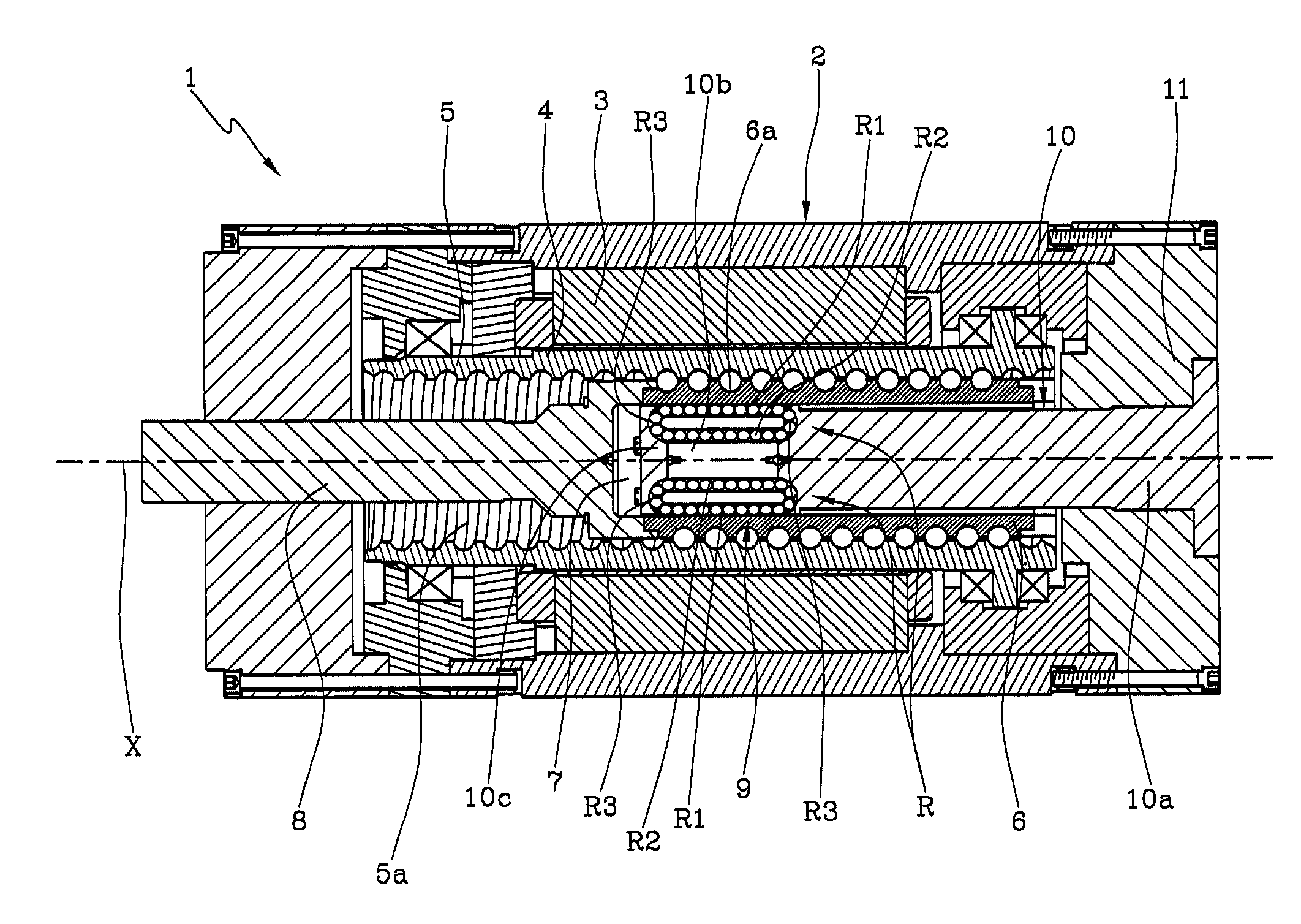
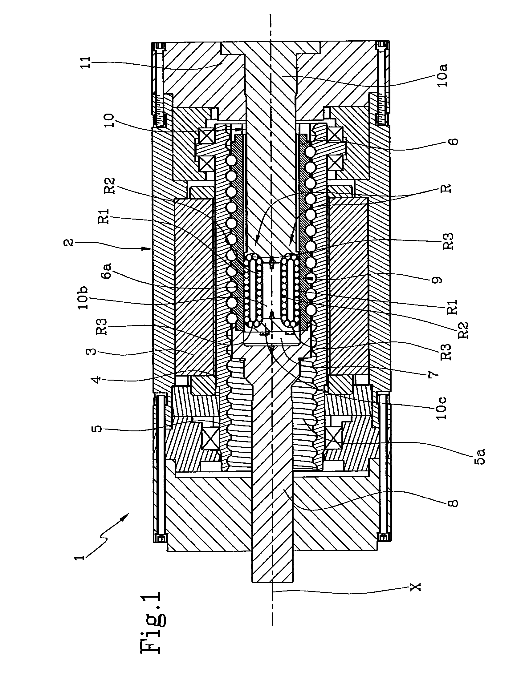
[0017]With reference to the accompanying drawings, the numeral 1 denotes in its entirety a linear electro-mechanical actuator according to the invention.

[0018]The actuator according to this description and as illustrated in the accompanying drawings is of the single-acting type, however, the inventive concept could also be applied to an actuator of the double-acting type.

[0019]As shown in FIG. 1, the actuator 1 comprises a rigid containment structure 2 housing an electric motor, in particular an outer stator 3 and a rotor 4 positioned inside the stator 3.

[0020]Inside the rotor 4, and in rigid connection with it, there is a nut 5 having an axis of rotation “X” which coincides with the axis of the rotor 4. The nut 5 is therefore rotated by the electromagnetic interaction between rotor 4 (usually of the permanent magnets type) and stator 3.

[0021]In the embodiment illustrated, the nut 5 has a main line of extension coinciding with the above-mentioned axis “X”.

[0022]The nut 5 is only ena...


PUM


Abstract

A linear electro-mechanical actuator includes a containment structure (2), a nut (5) positioned in the containment structure (2), a screw shaft (6) inserted in the nut (5) and interconnected with the nut (5) via a helical recirculating ball coupling, and an anti-rotation mechanism (9) positioned inside the screw shaft (6) to prevent the screw shaft (6) from rotating about the axis (X). The anti-rotation mechanism (9) includes a guide unit (10) fixed cantilever-style to the containment structure (2) and connected to the screw shaft by a non-rotational coupling.

Description

TECHNICAL FIELD[0001]This invention relates to a linear electro-mechanical actuator, in particular of the recirculating ball type.[0002]Linear electro-mechanical actuators usually have an electric motor whose stator is connected to a screw device (for example of the recirculating ball type) designed to transform the rotary movement of the rotor into a linear advancing movement of a pusher forming part of the screw device.[0003]So that the above-mentioned pusher (translating element of the screw device) can be provided with only linear translating motion, the linear electro-mechanical actuator must be equipped with an anti-rotation system which, for the equilibrium of the forces, balances the torque generated by the electric motor.BACKGROUND ART[0004]Prior art anti-rotation systems are described, for example, in the patent publications JP2002-54708 and JP59-19762 and DE202008001576U and use anti-rotation structures forming part of the actuator or stably connected to it.[0005]The trad...

Claims


Application Information

Patent Timeline
Patent Type & Authority Applications(United States)
IPC IPC(8): H02K7/06
CPCH02K7/06F16H25/20F16H25/2204F16H2025/204F16H2025/2078
Inventor PIZZONI, LUCIANOBEFFA, ROMANOMACCAGLIA, RICCARDOBORGARELLI, NICOLAPICONE, RAFFAELE
Owner UMBRAGRP SPA
Why Eureka
Try Eureka