

Battery fuse-containing box
- Summary
- Abstract
- Description
- Claims
- Application Information
AI Technical Summary
Benefits of technology
Problems solved by technology
Method used
Image

Examples
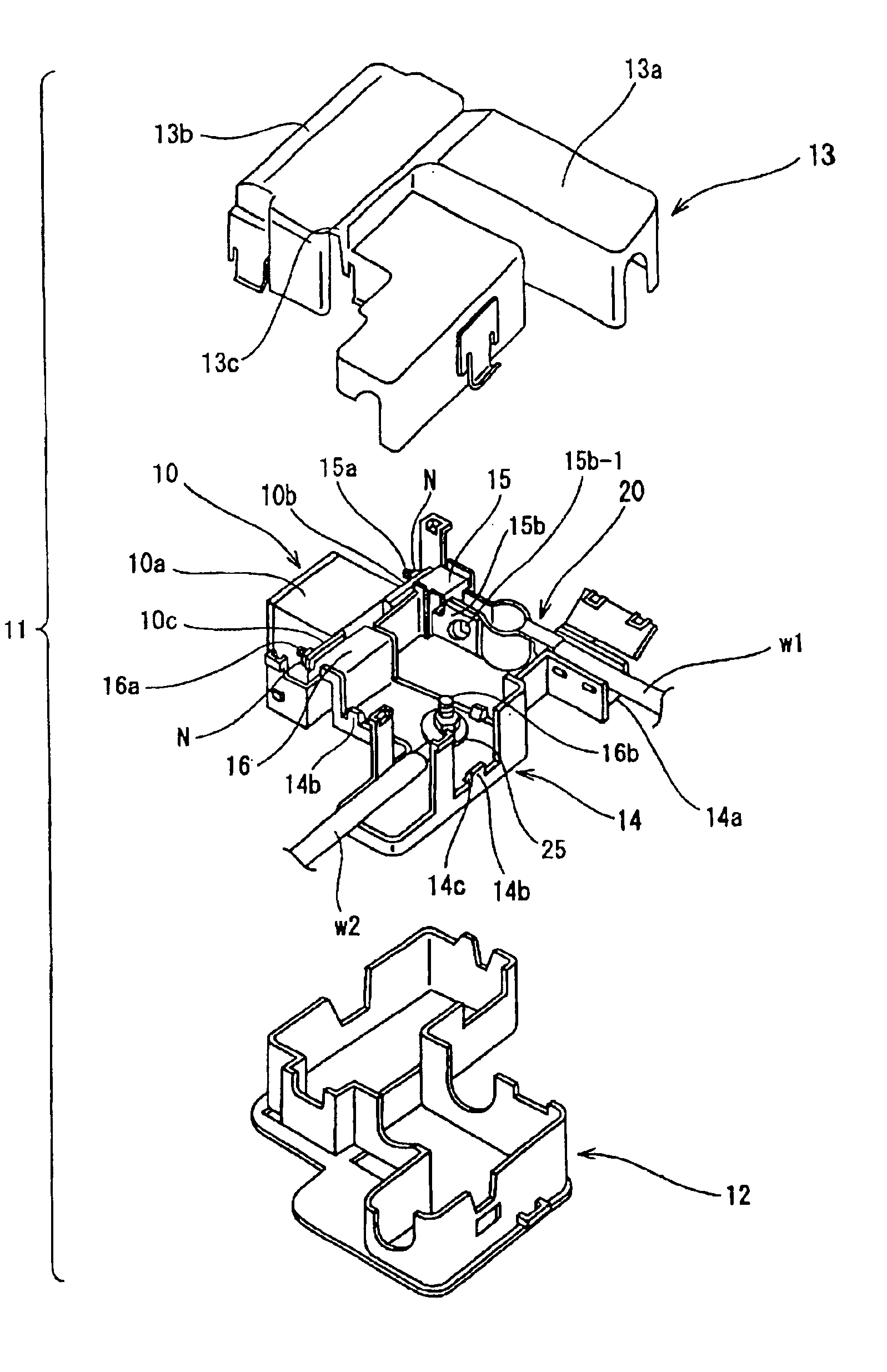
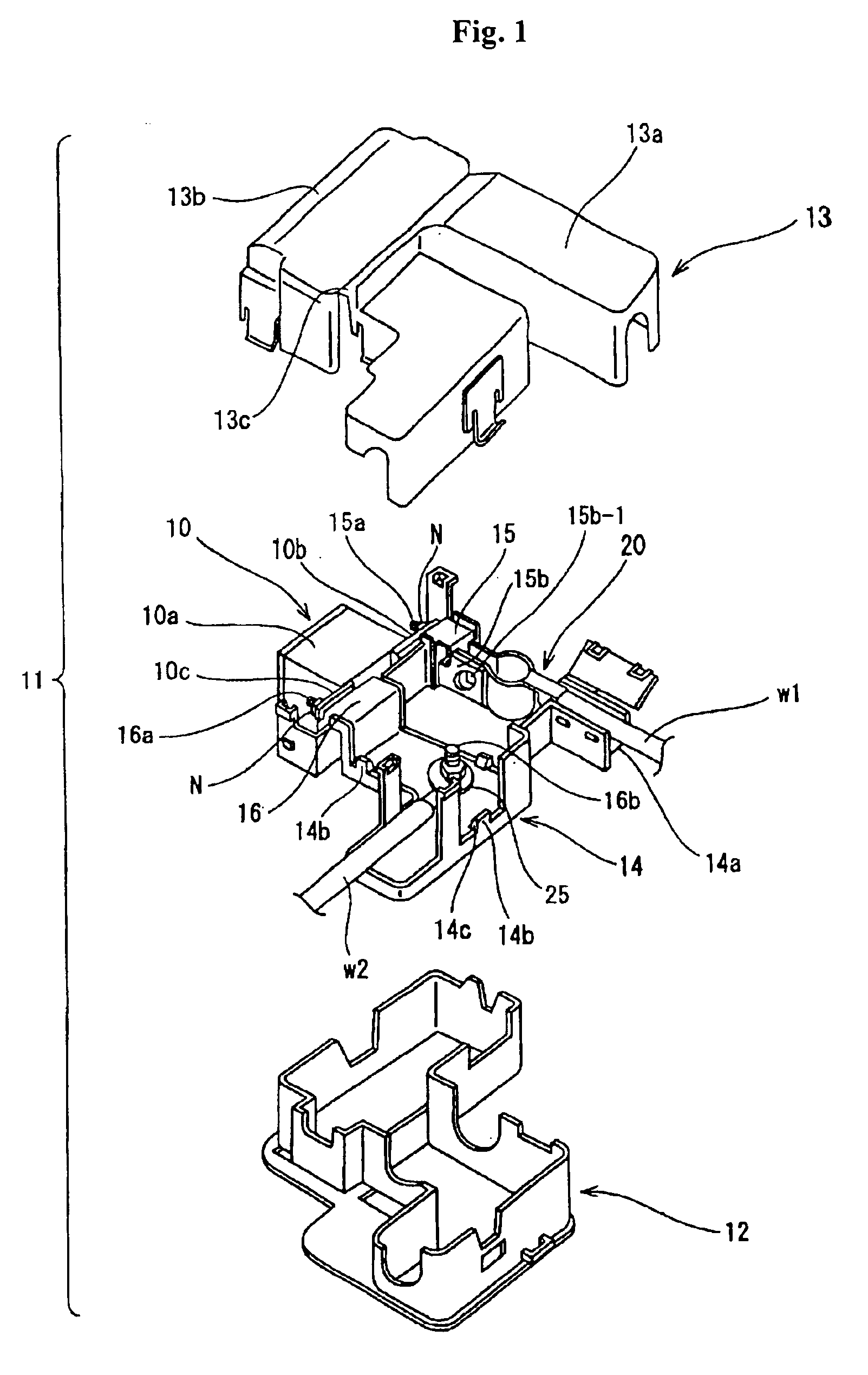
case 13
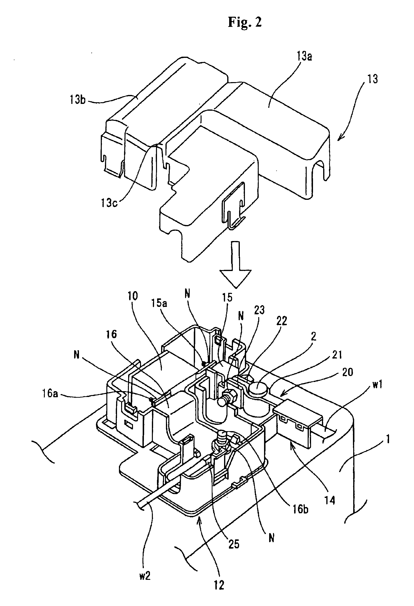
[0042]Upper case 13 has a first half which serves as an opening / closing lid 13a. Upper case 13 has a second half 13b that locks to lower case 12. A hinge 13c is interposed between the opening / closing lid 13a and the second half 13b to open and close the opening / closing lid 13a.
[0043]The battery terminal 20 has a projected circular-arc portion 21 which is crimped to the tip of an electric wire w1 of a power circuit and also fits on the periphery of the battery post 2. Circular-arc portion 21 has fastening pieces 22 and 23 that project from the tips of the circular-arc portion 21 at opposite sides. A bolt opening (not shown) is formed on each of the fastening pieces 22 and 23.
[0044]As shown in FIG. 5, the electric wire w1 is accommodated in an electric wire accommodation portion 14a of the supporting plate 14. An opening 19 is formed on the supporting plate 14 and the lower case 12 at a position corresponding to the position of the circular-arc portion 21, of the battery terminal 20,...
PUM
 Abstract
Description
Claims
Application Information