Machine tool

a technology of machine tools and parts, applied in the field of machine tools, can solve the problems of limited knowledge of each of the machine tools known in the prior art, and achieve the effects of high tooling density, easy adjustment of multiple process types, and ability to complete a complex par

Inactive Publication Date: 2005-09-27
MFR & TRADERS TRUST COMPANY AS AGENT
View PDF12 Cites 21 Cited by
  • Summary
  • Abstract
  • Description
  • Claims
  • Application Information

AI Technical Summary

Benefits of technology

[0015]Accordingly, the general object of the present invention is to provide an improved machine tool which allows for relative movement in a combination of axes.
[0016]Another object of the invention is to provide a machine tool which will easily accommodate multiple process types.
[0017]Another object of the invention is to provide a machine tool which allows for the interchangeable use of a high number of tools.
[0018]Another object of the invention is to provide a machine tool which has the ability to finish a complex part complete.
[0019]Another object of the invention is to provide a machine tool which allows for multiple cutting configurations.
[0020]Another object of the invention is to provide a machine tool which allows for high tooling density.

Problems solved by technology

However, each of the machine tools known in the prior art are limited in the type of cutting that they perform.
This limitation arises in large part from the fact that each machine only operates in a limited number of axes.

Method used


Image

  • Machine tool
  • Machine tool
  • Machine tool

Examples


Embodiment Construction

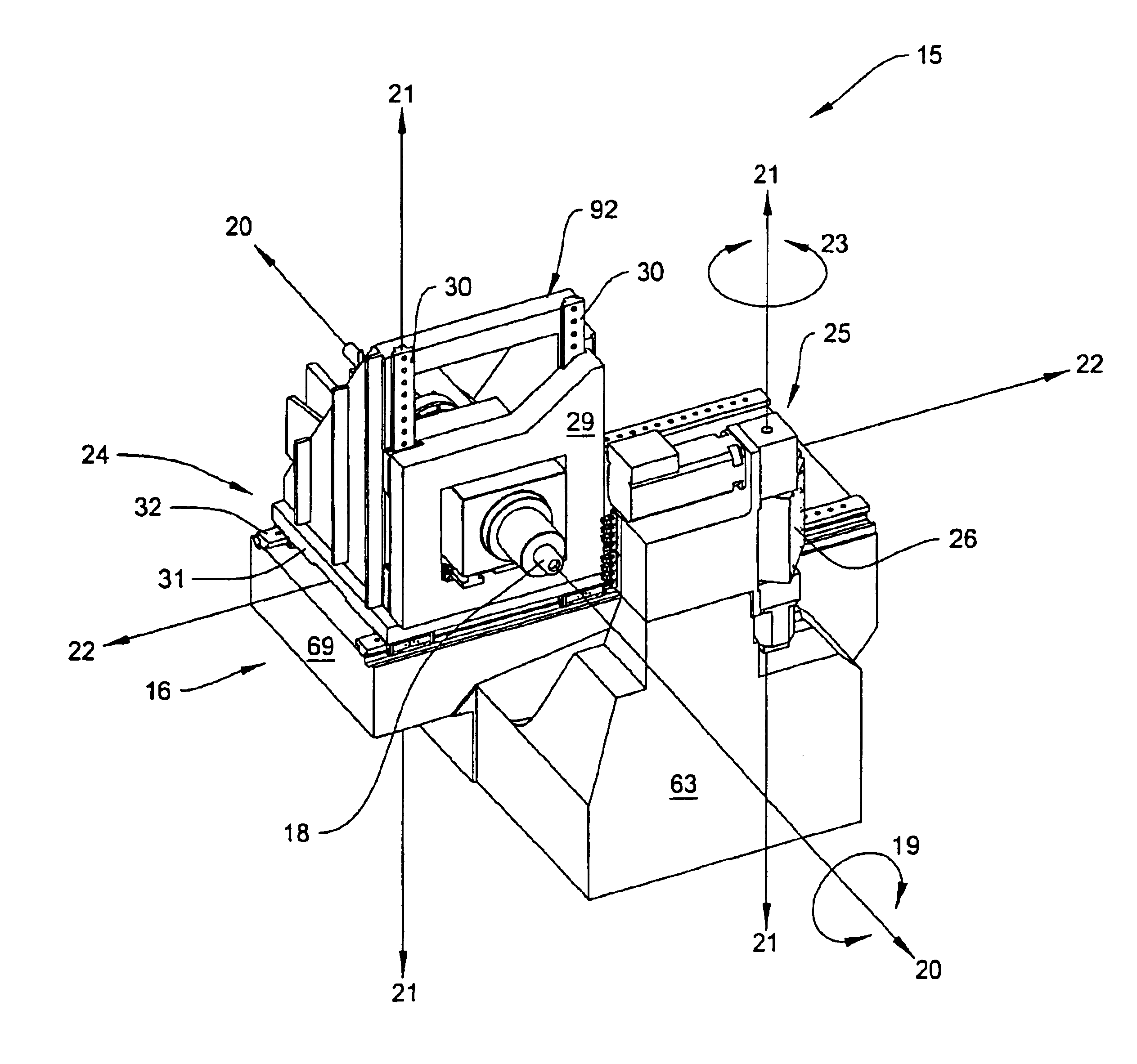
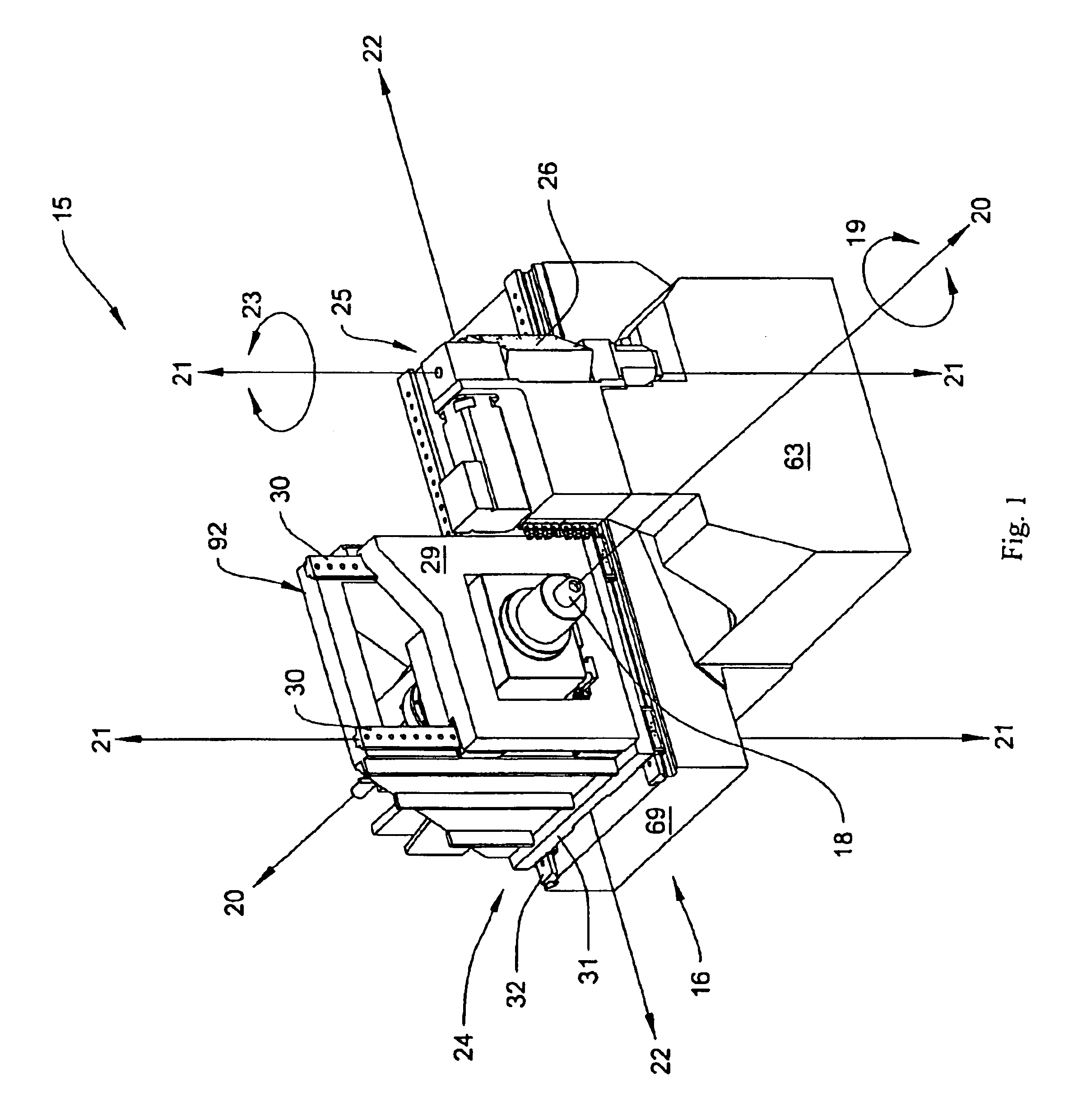
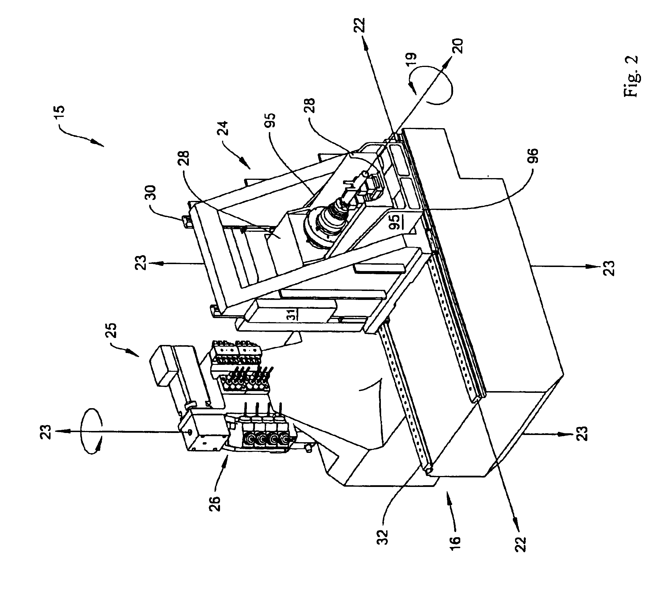
[0065]At the outset, it should be clearly understood that like reference numerals are intended to identify the same structural elements, portions or surfaces, consistently throughout the several drawing figures, as such elements, portions or surfaces may be further described or explained by the entire written specification, of which this detailed description is an integral part. Unless otherwise indicated, the drawings are intended to be read (e.g., cross-hatching, arrangement of parts, proportion, degree, etc.) together with the specification, and are to be considered a portion of the entire written description of this invention. As used in the following description, the terms “horizontal”, “vertical”, “left”, “right”, “up” and “down”, as well as adjectival and adverbial derivatives thereof (e.g., “horizontally”, “rightwardly”, “upwardly”, etc.), simply refer to the orientation of the illustrated structure as the particular drawing figure faces the reader. Similarly, the terms “inw...


PUM

PropertyMeasurementUnit
90 degree rotationaaaaaaaaaa
angleaaaaaaaaaa
densityaaaaaaaaaa

Abstract

An improved machine tool having a support structure (16), a spindle (18) rotatably supported by the structure, the spindle adapted for engagement with a workpiece (56), the spindle operatively arranged to selectively rotate in an annular A-axis (19) and about a linear Z-axis (20), a tool frame (25) supported by the structure, the tool frame having an array of individual tool-holding stations adapted for engagement with a tool (49), an actuating mechanism (24), the actuating mechanism operatively arranged to selectively provide movement of the workpiece in the spindle relative to the tool in the tool frame in the Z-axis, in a linear Y-axis (21) that is perpendicular to the Z-axis, and in a linear X-axis (22) that is perpendicular to both the Z-axis and the Y-axis, the position of the stations in the array defined by at least an X-axis coordinate and a Y-axis coordinate, at least two of the stations in the array positioned such that the two stations have neither the same X-axis coordinate nor the same Y-axis coordinate. The tool frame may comprise a tool frame actuating portion operatively arranged to selectively rotate in an annular axis that is about a linear axis that is not the Z-axis, and the annular axis may be a B-axis that is about the Y-axis.

Description

TECHNICAL FIELD[0001]The present invention relates generally to the field of machine tools and, more particularly, to a machine tool having increased operational versatility.BACKGROUND ART[0002]A number of types of machine tools are known and used in the prior art. Such machine tools generally fall into the three categories.[0003]The first category can be broadly described as turret-based turning machines. An example of this type of tool is the QUEST multi-tasking turning center provided by Hardinge Inc. of Elmira, N.Y. Generally, these machine tools are provided with a spindle and a turret on which tooling is mounted. The workpiece is either fed in bar stock through the spindle or a chuck is used to hold an individual workpiece slug in place. Generally, this type of machine tool operates in the X-axis, Z-axis and A-axis, although optional operation in the Y-axis can be provided;[0004]A second category of machines are generally referred to as Swiss-turning machines. An example of th...

Claims


Application Information

Patent Timeline
Patent Type & Authority Patents(United States)
IPC IPC(8): B23Q1/25B23Q1/62B23Q3/155B23Q39/02
CPCB23K26/1482B23Q1/626B23Q3/15513B23Q39/024Y10T483/16Y10T29/5114Y10T483/1702Y10T82/2552B23Q2039/004
Inventor SOROKA, DANIEL P.SHEEHAN, TERRANCEWASSON, KEVIN L.ERVIN, J. PATRICK
Owner MFR & TRADERS TRUST COMPANY AS AGENT
Why Eureka
Try Eureka