Fault-tolerant electric motor control system

a technology of fault-tolerant electric motors and control systems, applied in the direction of electronic commutation motor control, motor/generator/converter stoppers, dynamo-electric converter control, etc., can solve the problem of higher design and operation costs

Inactive Publication Date: 2005-09-27
BLUWAV SYST LLC
View PDF19 Cites 27 Cited by
  • Summary
  • Abstract
  • Description
  • Claims
  • Application Information

AI Technical Summary

Benefits of technology

[0006]The present invention offers a novel control system for a multiphase motor that does not need redundant elements in order to continue its operation when a phase fails. In the event of a phase failure, the control system of the present invention enables the motor to operate without a need to carry out any fault correction procedure.
[0007]Moreover, the control system of the present invention gives the user high flexibility by providing a choice between operating without fault correction or performing an appropriate fault correction procedure. In addition, fault-correction parameters defining motor characteristics when a phase is lost may be customized in accordance with user's preferences.

Problems solved by technology

Hence, the redundancy is provided at the expense of complex winding patterns causing higher cost of design and operation.

Method used


Image

  • Fault-tolerant electric motor control system
  • Fault-tolerant electric motor control system
  • Fault-tolerant electric motor control system

Examples


Embodiment Construction

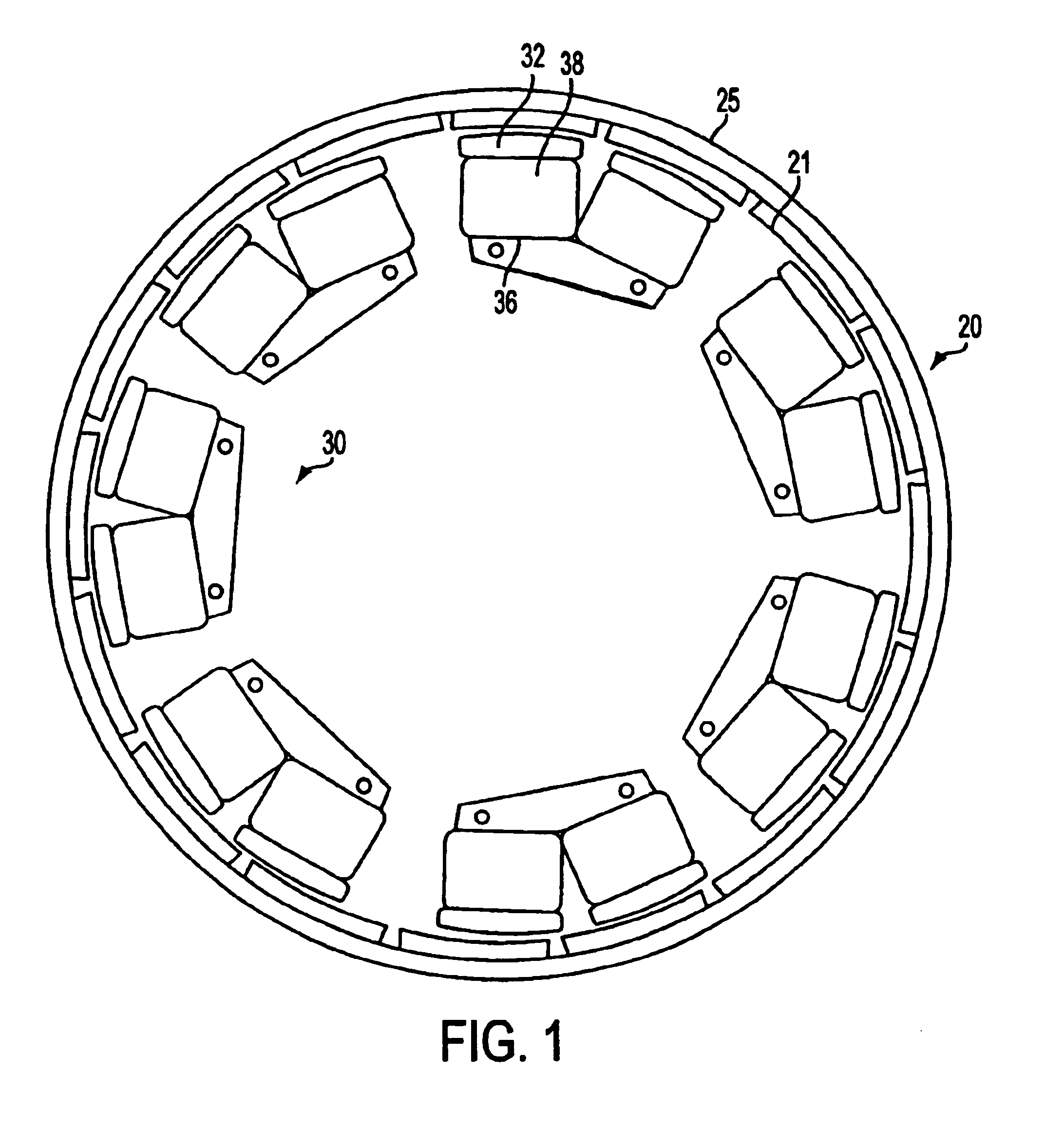
[0020]The present invention is applicable to controlling an electric motor such as disclosed in the copending U.S. application Ser. No. 09 / 826,422 of Maslov et al., filed Apr. 5, 2001 and incorporated herewith by reference, although the invention can be used with various other permanent magnet motors and switched-reluctance motors. FIG. 1 is an exemplary view showing rotor and stator elements of a motor 10 as described in that application, the disclosure of which has been incorporated herein. Rotor member 20 is an annular ring structure having permanent magnets 21 substantially evenly distributed along cylindrical back plate 25.

[0021]The permanent magnets are rotor poles that alternate in magnetic polarity along the inner periphery of the annular ring. The rotor surrounds a stator member 30, the rotor and stator members being separated by an annular radial air gap. Stator 30 comprises a plurality of electromagnet core segments of uniform construction that are evenly distributed alon...


PUM


Abstract

The present invention offers a novel control system for a multiphase motor. The control system involves energization circuitry for energizing each phase winding, and a control circuit for defining phase currents for individual phases of the motor to generate control signals applied to the energization circuitry for energization of the phase windings. When at least one phase of the motor fails, a mode selection circuit enables the control circuit to operate either in a non-correction mode or in a fault-correction mode. In the non-correction mode of operation, phase currents for phases that remain operational are maintained unmodified. In the fault-correction mode, the phase currents for the remaining phases are modified in accordance with pre-set parameters.

Description

FIELD OF THE INVENTION[0001]The present application relates to electric motors, and in particular, to a control system for providing fault-tolerant operation of a multiphase electric motor.BACKGROUND OF THE INVENTION[0002]For an electric motor that performs critical functions, for example in military applications, it is essential that the motor continues its operation even in the event of a failure of a phase. Therefore, comprehensive fault tolerance becomes a major aspect of the motor design. Conventionally, a motor is equipped with redundant elements to support fault-tolerant operation.[0003]For example, U.S. Pat. No. 4,434,389 discloses a brushless DC motor having a permanently magnetized rotor and a stator with redundant sets of windings. The rotor is formed with four or more magnetic poles. Two sets of stator windings being used in a four-pole motor, three sets being used in a six-pole motor, and four sets being used in an eight-pole motor. The windings in each set are connecte...

Claims


Application Information

Patent Timeline
Patent Type & Authority Patents(United States)
IPC IPC(8): H02P6/00H02P29/02H02P6/12
CPCH02P6/002H02P29/02H02P6/12H02P6/28H02P7/06
Inventor MASLOV, BORIS A.YUAN, GUOHUI
Owner BLUWAV SYST LLC
Why Eureka
Try Eureka