Smart airport automation system

a technology of airport automation and automation system, applied in the field of air traffic and flight operations control systems, can solve the problems of ineffectiveness, ineffectiveness, and inability to meet the needs of pilots, and achieve the effects of reducing runway incursions and mid-air conflicts, enhancing pilot situation awareness, and reducing the number of runway incursions

Inactive Publication Date: 2005-09-27
ARCHITECTURE TECH +1
View PDF4 Cites 89 Cited by
  • Summary
  • Abstract
  • Description
  • Claims
  • Application Information

AI Technical Summary

Benefits of technology

[0008]An advantage of the present invention is that a smart airport automation system is provided that enhances pilot situation awareness in airport terminal areas.
[0009]Another advantage of the present invention is that a smart airport automation system is provided that helps raise pilot awareness of aircraft in the air or on the runway and may thereby reduce runway incursions and mid-air conflicts.
[0010]A further advantage of the present invention is that a smart airport automation system provides efficiently fused information from disparate sources and then distributes this information in various formats to various users in order to increase safety and efficiency in the area around a non-towered airport.
[0011]Another advantage of the present invention is that it provides airport situational awareness to the surrounding air traffic management system for their monitoring of airports with or without radar surveillance.

Problems solved by technology

But some control towers are closed at night.
Other airports are so small, or used so infrequently, that there never was a control tower installed so there never are any air traffic controllers on-hand.
Current procedures, methods and operating practices are expensive, inefficient and adversely affect the commercial operation of air transportation services.

Method used


Image

  • Smart airport automation system
  • Smart airport automation system
  • Smart airport automation system

Examples


Embodiment Construction

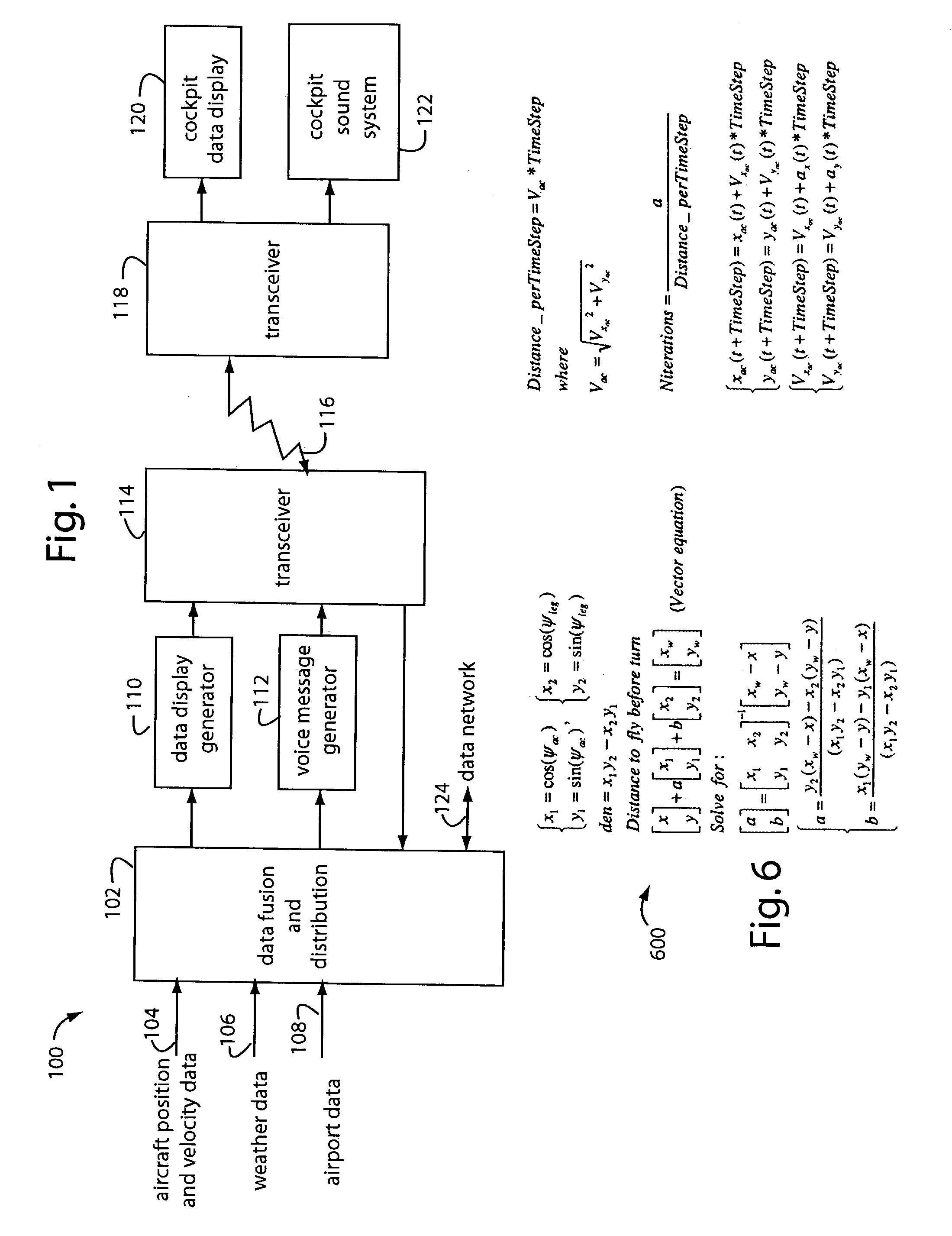
[0021]FIG. 1 illustrates a smart airport automation system embodiment of the present invention, and is referred to herein by the general reference numeral 100. The system 100 gathers a wide variety of data and information from many different types of sources and in many different formats. It then interprets, fuses and structures information for use in real-time by pilots, e.g., especially those approaching or leaving non-towered airports. Such information is also useful to air traffic controllers overseeing non-towered airport operations.

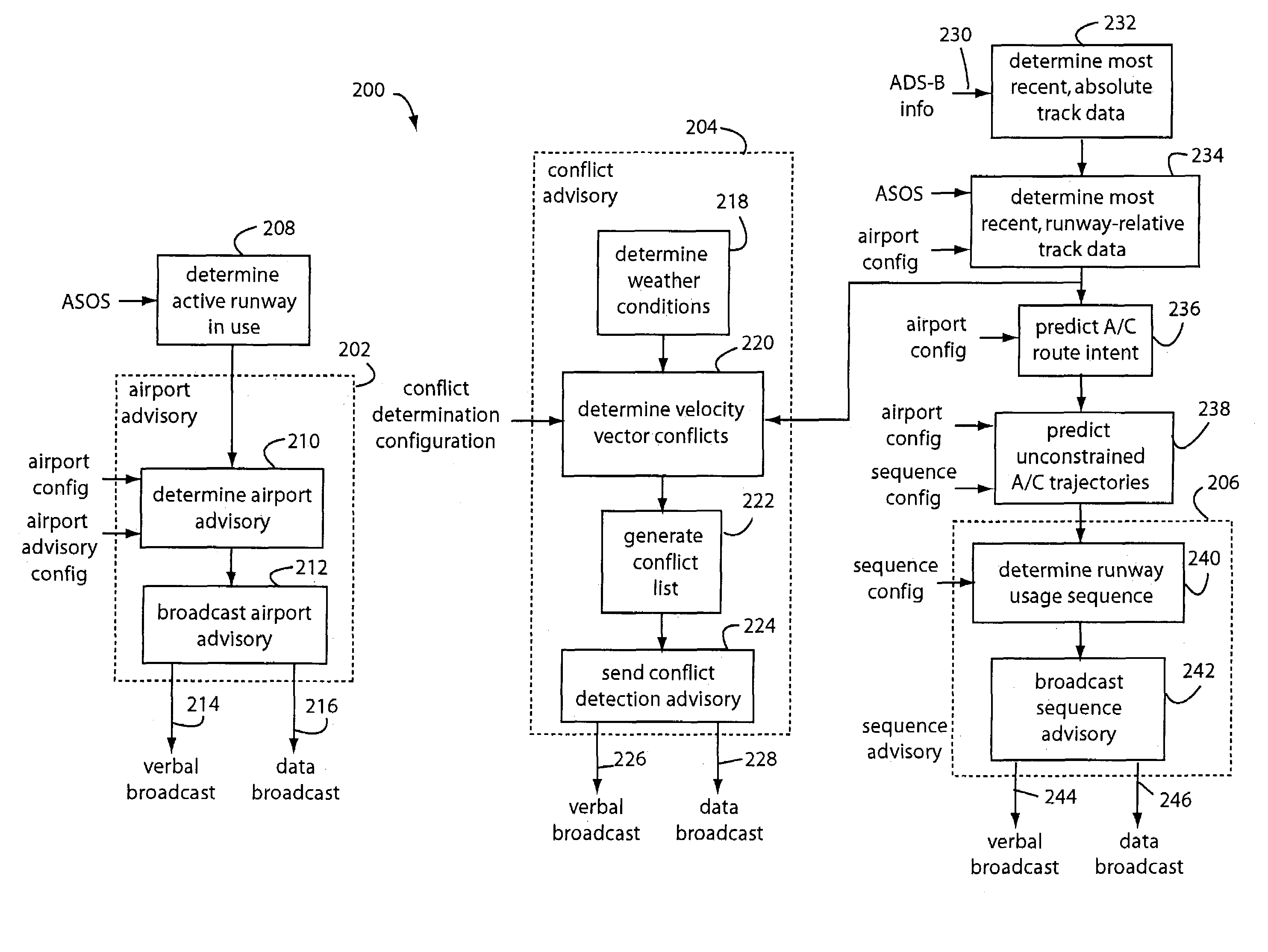
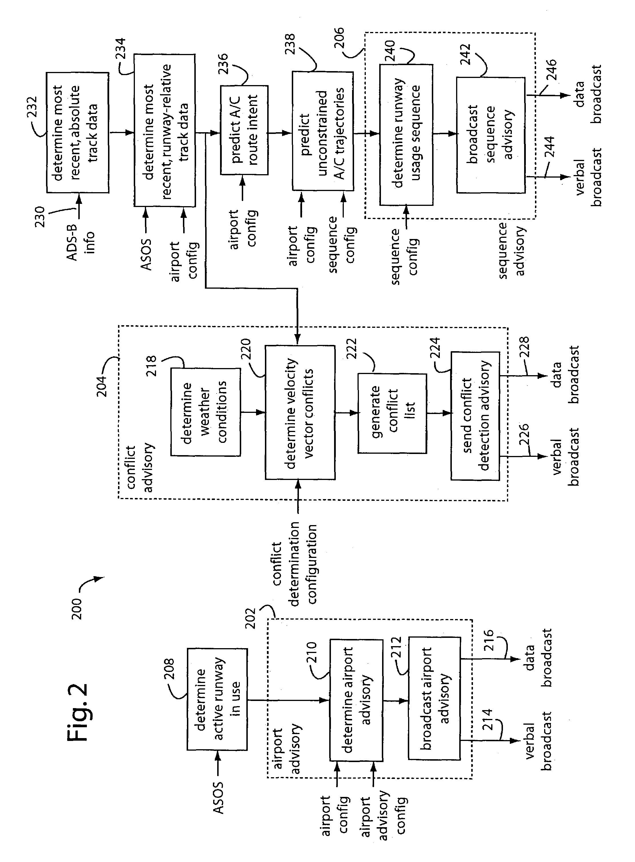
[0022]A data fusion and distribution computer 102 is provided with aircraft-position-and-velocity data inputs 104, weather data inputs 106, and airport data inputs 108. These are processed into structured information, e.g., airport advisories, takeoff and landing sequences for participating aircraft, separation distance thresholds between sequential aircraft, separation monitoring, and conflict detection. Such processing outputs information organize...


PUM


Abstract

A smart airport automation system includes a subsystem that inputs weather and airport configuration data to determine an active runway in use and an airport state. Another subsystem inputs aircraft position and velocity data from available surveillance sources, known flight-intent information, and past aircraft trajectories to project future aircraft unconstrained trajectories. A third subsystem uses the projected trajectories and aircraft intent to determine desired landing and takeoff sequences, and desired adjacent aircraft spacing. A fourth subsystem uses such information to predict potential aircraft conflicts, such as a loss of acceptable separation between adjacent aircraft. A fifth subsystem packages the weather, airport configuration, aircraft state, desired landing / takeoff sequence, and potential conflict detection into a verbal advisory message that is broadcast on a local common radio frequency. A sixth subsystem uses the projected trajectory information to control the runway and taxiway lighting system.

Description

FIELD OF THE INVENTION[0001]The present invention relates to air traffic and flight operations control systems, and more particularly to automated systems that collect, organize, retransmit, and broadcast airport and aircraft advisory information collected from sensors and other data sources.DESCRIPTION OF THE PRIOR ART[0002]Large, busy airports often include a control tower and staffed with air traffic controllers. Some airports are so busy the air traffic control is maintained 24-hours a day, and seven days a week. But some control towers are closed at night. Other airports are so small, or used so infrequently, that there never was a control tower installed so there never are any air traffic controllers on-hand.[0003]At a minimum, pilots flying in or out of airports need to know about other traffic in the area, runways to use, taxi instructions, weather, crosswind advisories, etc. When there is no control tower or staff, pilots must depend on their own sight and hearing, and then...

Claims


Application Information

Patent Timeline
Patent Type & Authority Patents(United States)
IPC IPC(8): G01S13/00G08B21/00G08G5/06
CPCG08G5/0013G08G5/0026G08G5/0065G08G5/0082G08G5/025G08G5/0091
Inventor CLAVIER, ODILE H.SCHLEICHER, DAVID R.HOUCK, SHARON W.SORENSEN, JOHN A.DAVIS, PAUL C.HUNTER, CORNELIUS G.
Owner ARCHITECTURE TECH
Why Eureka
Try Eureka