Video image rotating apparatus

a rotating apparatus and video technology, applied in the direction of television systems, instruments, color signal processing circuits, etc., can solve the problems of not being able to achieve the viewing angle at all, the best view of pictures, and difficulty for several people wishing to view pictures at the same time from varied locations

Inactive Publication Date: 2005-09-27
360TV
View PDF9 Cites 7 Cited by
  • Summary
  • Abstract
  • Description
  • Claims
  • Application Information

AI Technical Summary

Benefits of technology

[0022]It is necessary that the video image be rotated through the optical means in sync with rotation of the projection screen so that the same video image in the same orientation may be viewed throughout the entire 360° arc during operation of the apparatus. This enables any viewer in the audience to periodically have a line of sight in alignment with a proper viewing angle for the projected image. When the rotational rate and revolutions per minute is sufficiently great, all viewers surrounding the video image rotating apparatus will see the same picture substantially simultaneously and continuously.

Problems solved by technology

The general problem in the display of a picture print, a television image or a projection onto a screen is that the picture is best viewed when the viewers line of sight is precisely normal to the plane of the picture.
When a viewer is not positioned directly in front of the television set, the best possible viewing angle is not achieved, or a viewing angle is not achieved at all.
Thus, it is difficult for several people wishing to view a picture simultaneously from varied locations.
Furthermore, placing four existing television sets back-to-back in an attempt to create a 360° viewing angle is rather costly as four television sets must be purchased.
A problem with such an arrangement is that the rotation of the picture must be relatively slow in order to permit the various viewers to have an opportunity to study the picture.
For example, during business meetings a group of executives typically sit around a conference table, an arrangement which does not readily enable information presented to be displayed to all in attendance.
In addition, the ability to display data through a 360° range would prevent members from looking at a series of pictures out of order, a potential problem if duplicate sets of pictures were to be provided to each individual member.
Another drawback associated with conventional display systems is that special consideration must be given to the positioning of the display within its environment because, typically, conventional display systems, such as a television, cannot be viewed from the rear or extreme sides.
Thus, the area within which a viewing audience can be accommodated is limited to locations with suitable sight lines.
As a result, use of the space available around the display system is often limited by the presence of blind spots.
Moreover, the positioning of furniture within the room can disadvantageously be dictated by a need to provide clear sight lines to a television or the like.
Such systems disclosed in these patents suffer from a visually perceptible blur at the edge of the projected image as it rotates past the viewer's line of sight.
This limits the proportion of the final image size with respect to the overall drum size of the apparatus.
Such electronic rotation system requires a fairly complex synchronization separator circuit, memory, and an algorithm-further complicating the device and adding increased costs.

Method used


Image

  • Video image rotating apparatus
  • Video image rotating apparatus
  • Video image rotating apparatus

Examples


Embodiment Construction

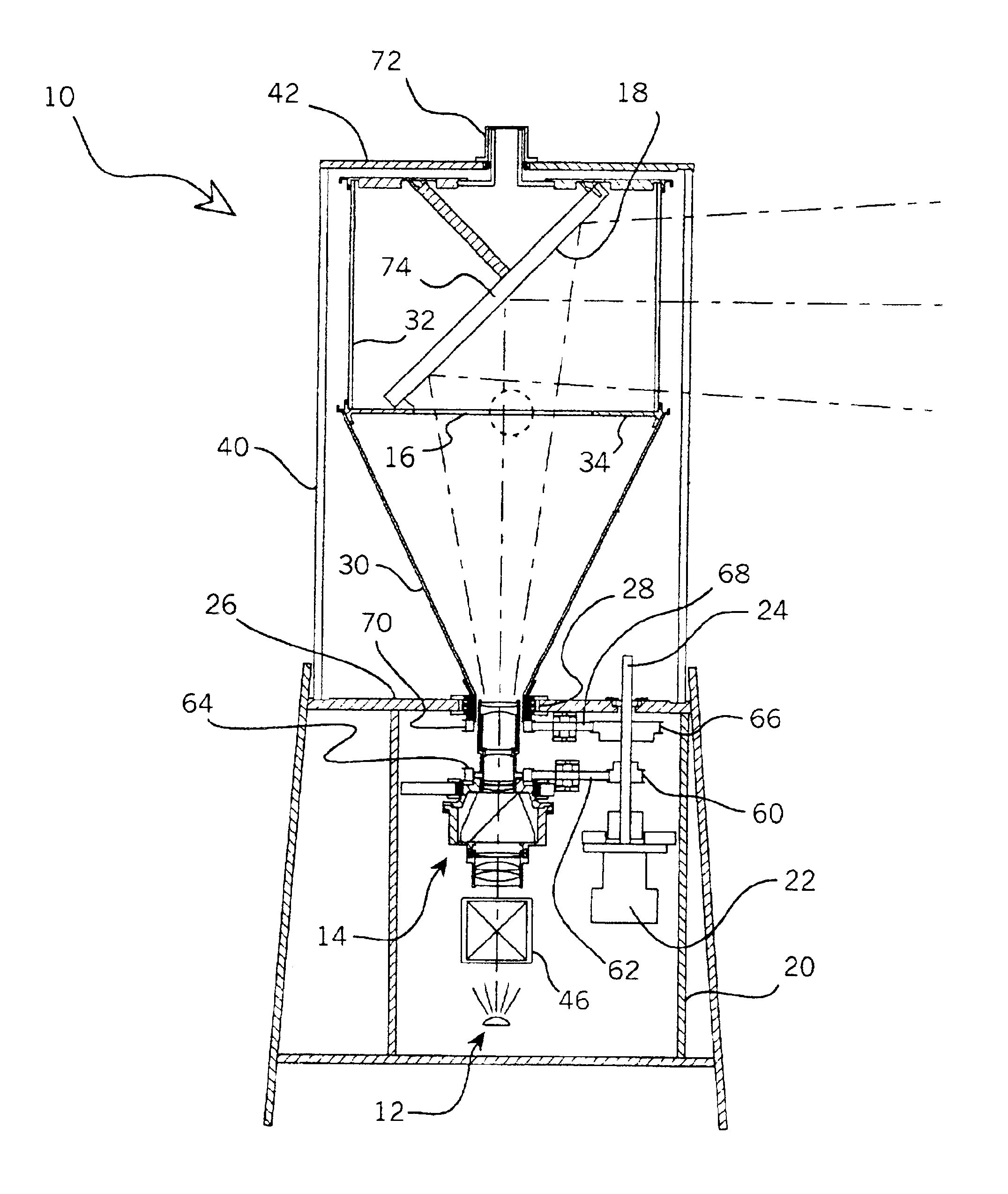
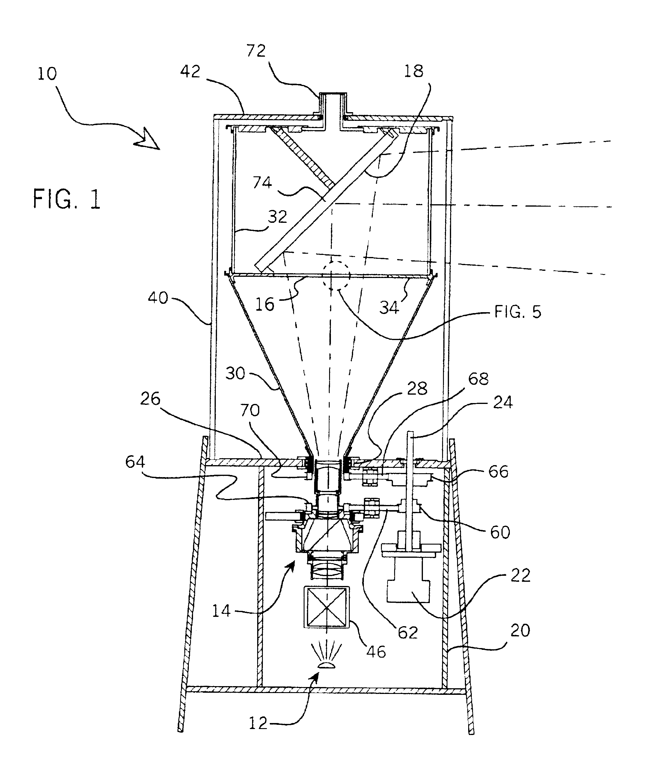
[0034]As shown in the drawings for purposes of illustration, the present invention resides in a video image rotating apparatus 10 which enables a video image to be viewed substantially simultaneously by an audience surrounding the apparatus through a 360° arc.

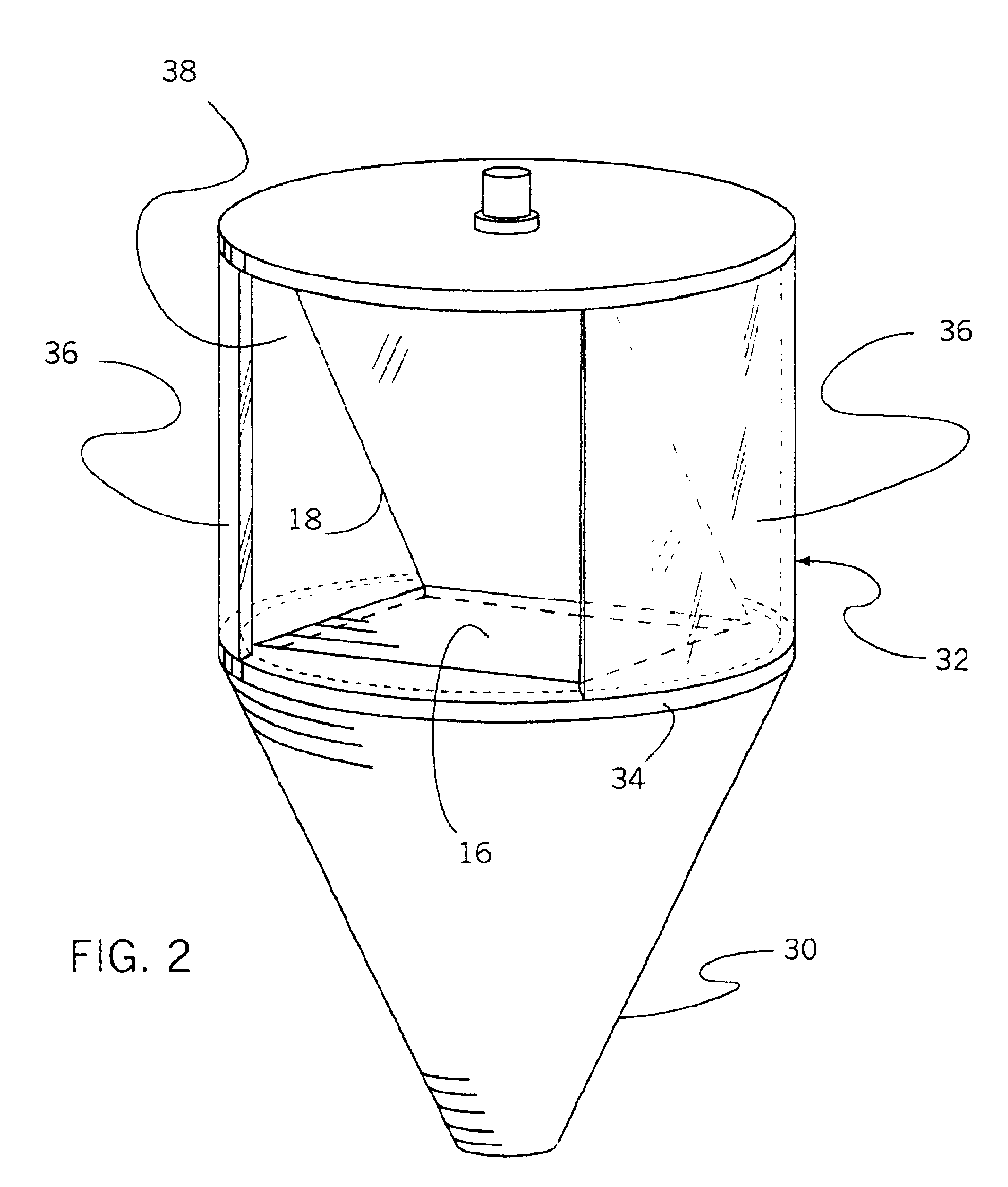
[0035]With reference to FIG. 1, the apparatus 10 generally includes a projector 12 which produces video images, a lens assembly 14 which receives the projected images from the projector 12 and directs the images onto a rear projection screen 16 which is disposed in a generally horizontal position. In order to simplify the design of the apparatus 10, the projector 12 and lens assembly 14 are vertically positioned directly below the rear projection screen 16 so as to be aligned therewith. A mirror 18 is angularly disposed over the rear projection screen 16 and reflects the video image to viewers. As will be described more fully herein, the video image is rotated in synchronization with the rotation of the screen 16 and mirror 18 ...


PUM


Abstract

A video image rotating apparatus includes a rear projection screen rotatably disposed in a generally horizontal plane, thus allowing only a single mirror to be angularly positioned over the screen to project video images to viewers. An optical system is positioned below the screen and vertically aligned therewith for projecting video images onto the screen. Preferably, the video images are mechanically rotated by rotating a portion of the optical system at a rate of rotation that is one-half that of the screen so that all viewers surrounding the video image rotating apparatus will see the same picture substantially simultaneously and continuously. Alternatively, the video images produced by the optical system may be rotated by an electronic image rotation system that electronically rotates the images produced in synchronization with rotation of the screen.

Description

RELATED APPLICATION[0001]The present invention claims priority from U.S. Provisional Application No. 60 / 284,341 filed Apr. 17, 2001.BACKGROUND OF THE INVENTION[0002]The present invention generally relates to image projection and television viewing systems. More particularly, the present invention relates to an apparatus for enabling a centrally located video image to be viewed substantially simultaneously by an audience surrounding the image through a 360° span.[0003]The general problem in the display of a picture print, a television image or a projection onto a screen is that the picture is best viewed when the viewers line of sight is precisely normal to the plane of the picture. Traditional television sets are relatively flat and square. These television sets must be positioned strategically within a room so that they are easily viewed by the viewers. When a viewer is not positioned directly in front of the television set, the best possible viewing angle is not achieved, or a vie...

Claims


Application Information

Patent Timeline
Patent Type & Authority Patents(United States)
IPC IPC(8): H04N5/74G03B21/28G03B21/62G09F19/18H04N9/31H04N9/64
CPCG03B21/28G03B21/625G09F19/18H04N9/3105H04N9/3141H04N9/3182H04N9/3197H04N9/64
Inventor LANE, MARC S.
Owner 360TV
Why Eureka
Try Eureka