Transmission of the fixed size PDUs through the transparent RLC

Active Publication Date: 2005-09-27
CORE WIRELESS LICENSING R L
View PDF17 Cites 98 Cited by
  • Summary
  • Abstract
  • Description
  • Claims
  • Application Information

AI Technical Summary

Benefits of technology

[0030](6) CS data, which uses transparent data services on the Iu interface, can be sent through UTRAN without adding any overhead on th

Problems solved by technology

There is, in fact, a conflict between emerging standards that creates a problem in this regard.
The more important issue is that the idea to use other than 10 ms in UTRAN has been presented for this traffic class.
So the main prob

Method used


Image

  • Transmission of the fixed size PDUs through the transparent RLC
  • Transmission of the fixed size PDUs through the transparent RLC
  • Transmission of the fixed size PDUs through the transparent RLC

Examples


Example

[0053]Normally the UE will activate a connection establishment request (ACTIVATE_PDP_CONTEXT_REQUEST) to the 3G-SGSN of FIG. 13 by requesting an IP Address (PDP_Address) and that inter alia a certain QoS be associated with the connection. The 3G-SGSN responds by sending a request (RAB_ASSIGNMENT_REQUEST) to the UTRAN to establish a Radio Access Bearer (RAB) to carry out the request. An RAB setup procedure is then carried out at the UTRAN between the RANAP and the RRC and once competed the RAB assignment of QoS profile and bearer ID are signaled (RAE_ASSIGNMENT_COMPLETE) back to the 3G-SGSN with QoS profile and bearer ID. The connection setup is then completed at the 3G-GGSN and signaled back to the UE via the 3G-SGSN with IP Address, QoS, Bearer ID and other information.

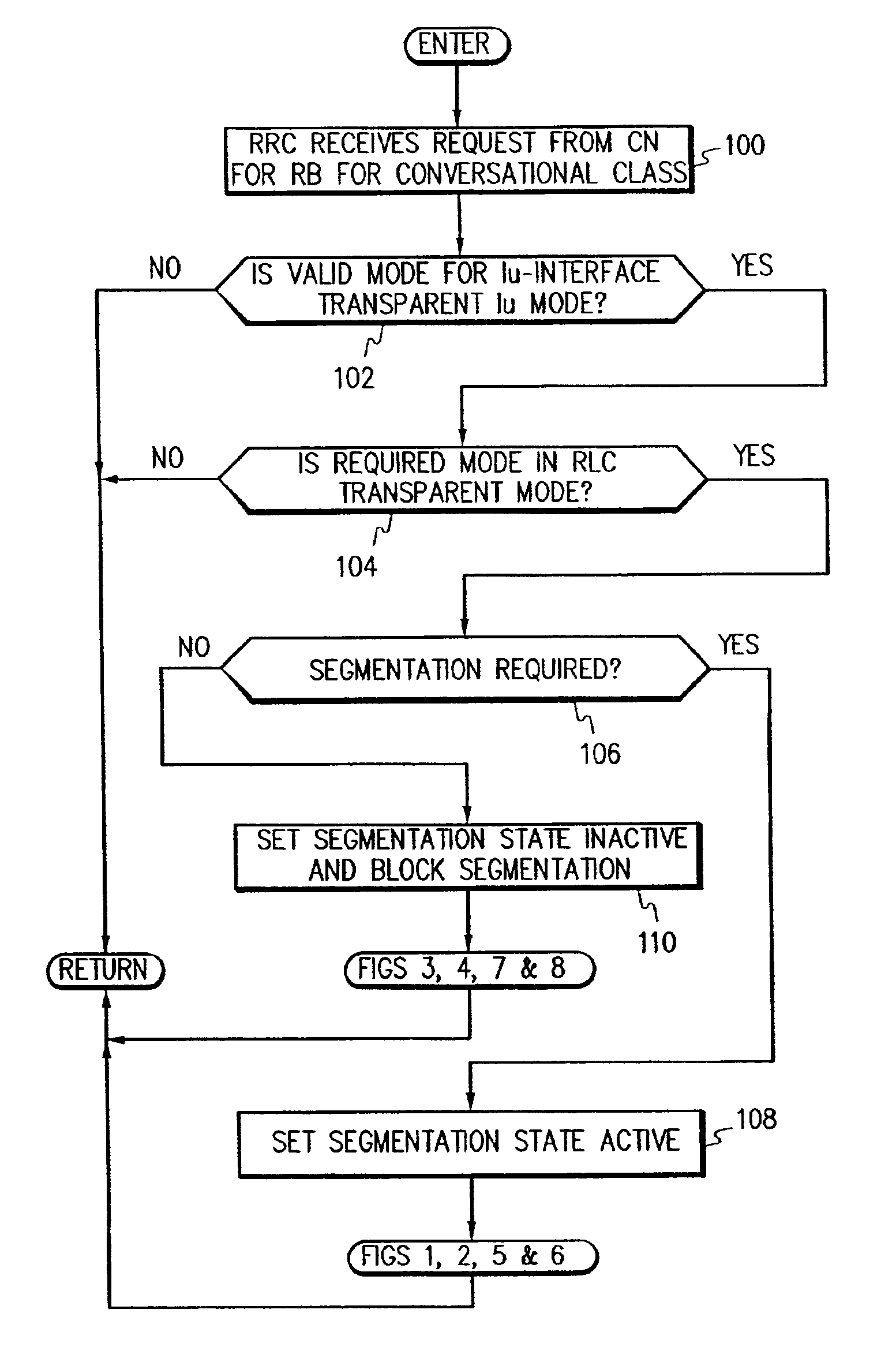
[0054]As shown for example beginning in a step 100 in FIG. 14, after the UE has requested of the CN (3G-SGSN) that a PDP context be activated, and upon reception of an RAB assignment request from the CN (3G-SGSN), th...


PUM


Abstract

Active and inactive segmentation states are defined for transparent mode for a radio access network (RAN) interfacing with a core network (CN) and a user equipment (UE). If transparent mode is valid on the Iu-interface between the RAN and the CN, then an inactive segmentation state indicates to peer (UE/RAN) segmentation and reassembly (SAR) entities such as at the radio link control (RLC) layer that segmentation is blocked in the UTRAN, over the Uu-interface, and in the UE so that TTIs with periodicities greater than the minimum transmission interval may be utilized, except over said Iu-interface.

Description

[0001]This application claims benefit of U.S. application Ser. No. 60 / 195,676 filed Apr. 7, 2000.BACKGROUND OF THE INVENTION[0002]Referring to FIG. 9, the Universal Mobile Telecommunications System (UMTS) packet network architecture includes the major architectural elements of user equipment (UE), UMTS Terrestrial Radio Access Network (UTRAN), and core network (CN). The UE is interfaced to the UTRAN over a radio (Uu) interface, while the UTRAN interfaces to the core network over an Iu interface. FIG. 10 shows some further details of the overall architecture. The Iu protocol includes a user plane (UP) protocol as shown in FIG. 11. A user plane protocol implements the actual radio access bearer service, i.e., carrying user data through the access stratum. Another way of looking at the user plane protocol is shown in FIG. 12. It is distinguished from the control plane protocol of FIG. 13 that controls the radio access bearers and the connection between the UE and the network from diffe...

Claims


Application Information

Patent Timeline
IPC IPC(8): H04Q7/30H04Q7/38H04W72/12H04W76/04H04W92/04
CPCH04W28/065H04W92/045H04W76/04H04W76/20H04W92/04H04L12/00
Inventor SARKKINEN, SINIKKAMIKOLA, JUHARINNE, MIKKO J.
Owner CORE WIRELESS LICENSING R L
Why Eureka
Try Eureka