Receiver having automatic burst mode I/Q gain and phase balance

a receiver and burst mode technology, applied in the field of balancing i/q gain and i/q phase in a signal receiver, can solve the problems of i/q gain and i/q phase to be out of balance, the bit error rate (ber) in estimating the transmitted data is affected, and the performance of the receiver using the test signal method is limited

Inactive Publication Date: 2005-09-27
RADIA COMM
View PDF5 Cites 19 Cited by
  • Summary
  • Abstract
  • Description
  • Claims
  • Application Information

AI Technical Summary

Benefits of technology

[0011]Advantages of the present invention are that no test signal is required, no communication overhead is added, and the correction coefficients are determined without degrading BER during the determination time period.

Problems solved by technology

However imperfections in the analog circuitry used in the radio frequency (RF) quadrature downconverters in most modern signal receivers cause the I / Q gain and I / Q phase to be out of balance (I / Q gain not equal to one and I / Q phase not equal to 90°).
These imbalances cause a degradation in bit error rate (BER) in estimating the transmitted data.
However, the performance of the receivers using the test signal method is limited by drift in the analog circuitry after the alignment.
However, the periodic alignment adds overhead that reduces the efficiency of a signal communication channel.
However, the BER performance of the receivers using the adaptive algorithm method is degraded because the receiver is estimating the transmitted data during the same on-line time period that the adaptive algorithm is converging.
Of course, the adaptive algorithm could be performed on a test signal but this would add overhead and reduce signal efficiency.
The performance of such receivers is limited because the imbalances are converted to image signals by the downconversion and / or demodulation and the degradation effect of such image signals cannot be completely eliminated once they are formed.

Method used


Image

  • Receiver having automatic burst mode I/Q gain and phase balance
  • Receiver having automatic burst mode I/Q gain and phase balance
  • Receiver having automatic burst mode I/Q gain and phase balance

Examples


second embodiment

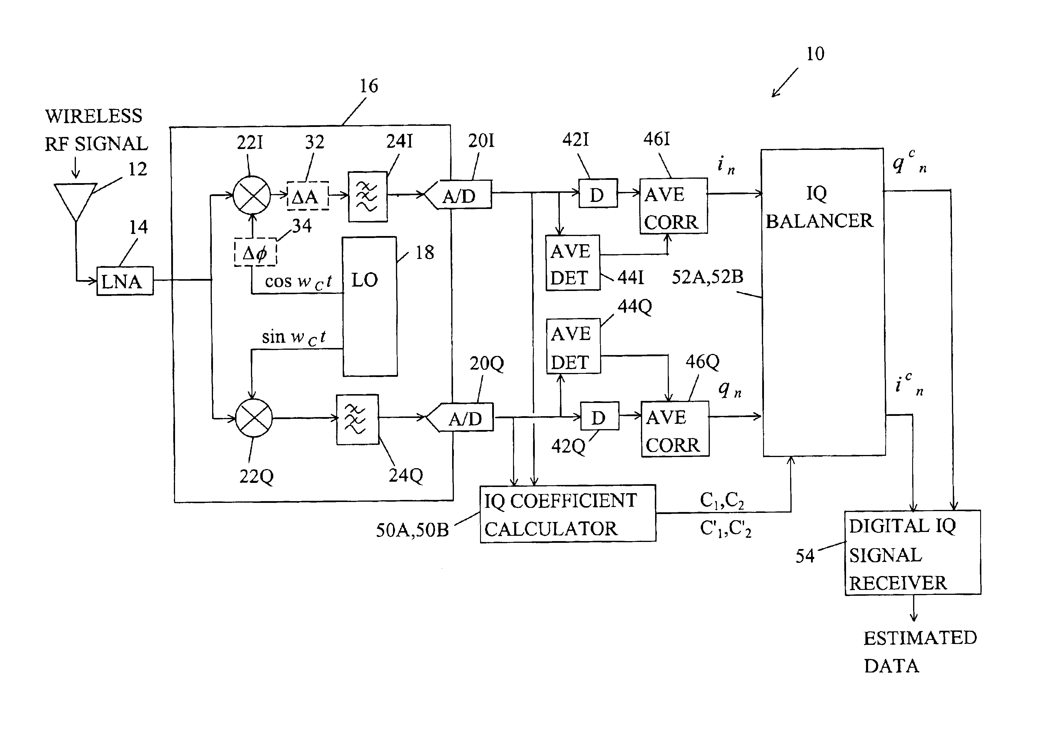
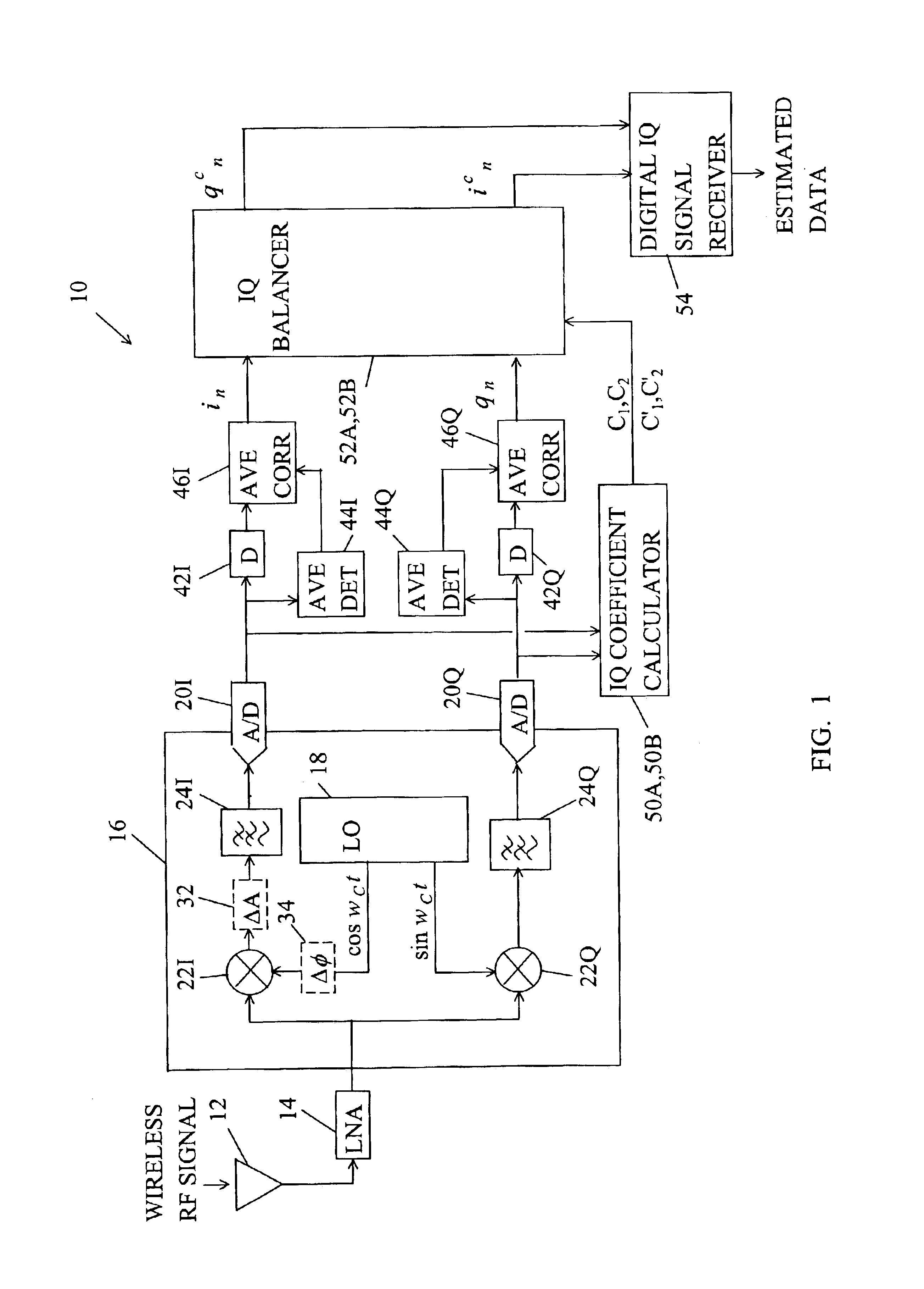
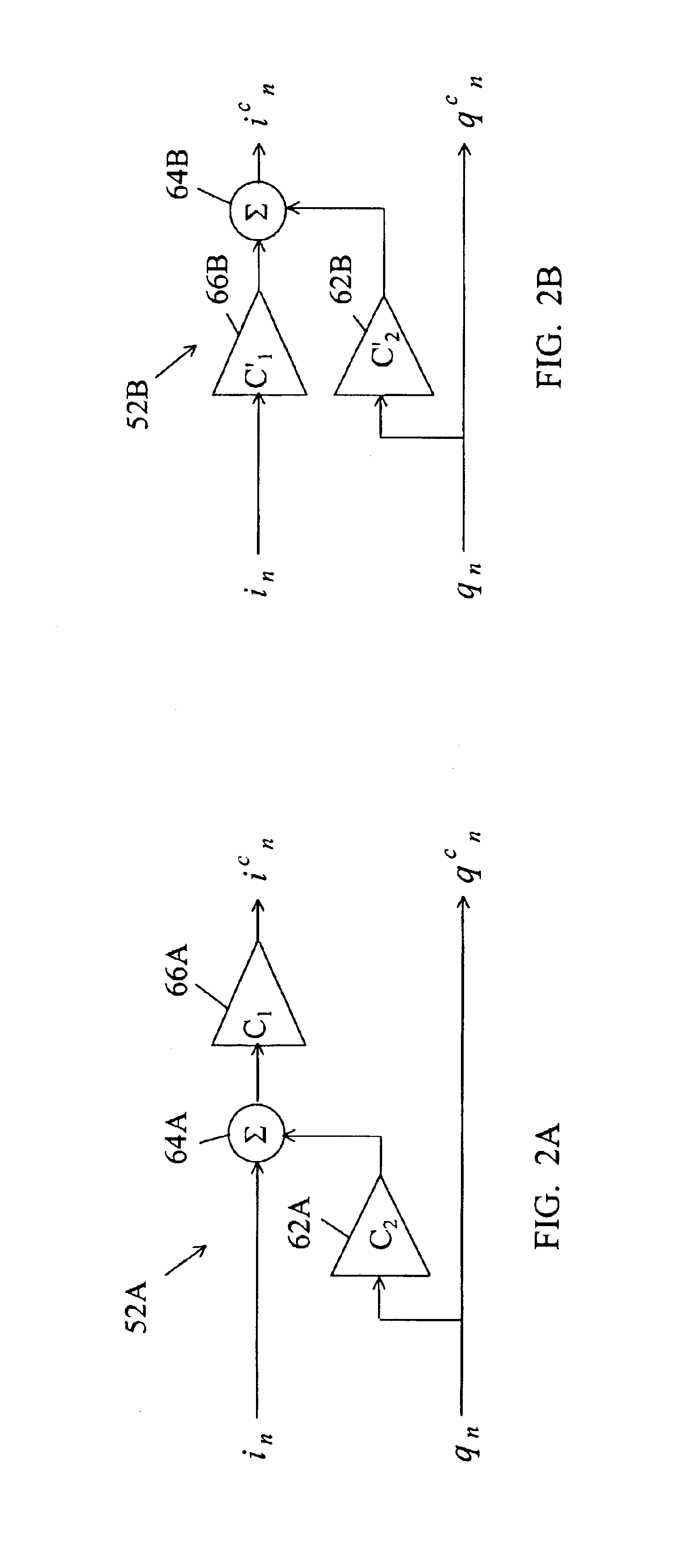
[0027]Similarly, the second embodiment IQ corrector 52B includes a phase balancer 62B, a summer 64B, and a gain balancer 66B. The phase balancer 62B multiplies the Q signal qn by the second coefficient C′2 and provides a phase correction signal C′2*qn to the summer 64B. The gain balancer 66B multiplies the I signal in by the first coefficient C′1 and provides an amplitude correction signal C′1*in to the summer 64B. The summer 64B adds the phase correction signal C′2*qn to the amplitude correction digital C′1*in and provides the corrected I signal icn=C′1*in+C′2*qn as the sum. The Q signal qn is passed straight through as the corrected Q signal qcn. Of course, the processing of the I and Q signals in and qn could be exchanged.

[0028]Simple algorithms for computing the correction coefficients in the IQ coefficient calculator 50A,B are described with the aid of equations 5-12. K1=∑n=1N⁢in⁢qn(5)K2=∑n=1N⁢qn⁢qn(6)K3=K1K2(7)K4=∑n=1N⁢qn(8)K5=∑n=1N⁢in-K3⁢qn(9)C1=C1′=K4K5(10) C2=−K3  (11)

C′2=−...

first embodiment

[0030]For the first embodiment where the IQ balancer 52A corrects I and Q signals according to icn=C1*(C2*qn+in) and qcn=qn, the IQ coefficient calculator 50A computes the first correction coefficient C, equal to the fourth term K4 divided by the fifth term K5 and computes the second correction coefficient C2 equal to the negative of the third term K3.

[0031]For the second embodiment where the IQ balancer 52B corrects the I and Q signals according to icn=C′1*in+C′2*qn and qcn=qn, the coefficient calculator 50B computes the first correction coefficient C′1 equal to the fourth term K4 divided by the fifth term K5 and computes the second correction coefficient C′2 equal to the negative of the product of the first coefficient C′1 times the third term K3.

[0032]It should be understood that it is equivalent to exchange the processing of the in and qn vectors for the equivalent result in the first embodiment and in the second embodiment.


PUM


Abstract

A method and apparatus for balancing I / Q gain and I / Q phase in a signal receiver. The receiver includes an IQ coefficient calculator, an IQ balancer, and a latency time delay device. The latency time delay device delays I and Q signals by a latency time period. During the latency time the IQ coefficient calculator uses the I and Q signals during a section of the packets corresponding to the latency time period for computing correction coefficients. The IQ balancer receives the I and Q signals after the latency time period and applies the correction coefficients to the entire packet of I and Q signals.

Description

BACKGROUND OF THE INVENTION[0001]1. Field of the Invention[0002]The invention relates generally to signal receivers having in-phase (I) and quadrature phase (Q) signal processing and more particularly to methods and apparatus for balancing I / Q gain and I / Q phase in a signal receiver.[0003]2. Description of the Prior Art[0004]Most modern radio signal receivers estimate the data that was transmitted by processing in-phase (I) and quadrature phase (Q) signal components. The I and Q signals should have a phase difference (I / Q phase) of 90° at the carrier frequency of the incoming signal and a gain ratio (I / Q gain) of unity. However imperfections in the analog circuitry used in the radio frequency (RF) quadrature downconverters in most modern signal receivers cause the I / Q gain and I / Q phase to be out of balance (I / Q gain not equal to one and I / Q phase not equal to 90°). These imbalances cause a degradation in bit error rate (BER) in estimating the transmitted data.[0005]Existing signal ...

Claims


Application Information

Patent Timeline
Patent Type & Authority Patents(United States)
IPC IPC(8): H04L27/38H04B1/30
CPCH04B1/30H04L27/3863
Inventor BROWN, JAMES E. C.
Owner RADIA COMM
Why Eureka
Try Eureka