Eureka AIR delivers breakthrough ideas for toughest innovation challenges, trusted by R&D personnel around the world.
Optically marked surface
Inactive Publication Date: 2005-09-27
SHAW CONTRACT FLOORING SERVICES
View PDF7 Cites 27 Cited by
Summary
Abstract
Description
Claims
Application Information
AI Technical Summary
This helps you quickly interpret patents by identifying the three key elements:
Problems solved by technology
Method used
Benefits of technology
[0021]Accordingly, the general object of the present invention is to provide an improved surface which may be marked by the illumination of optical material such that the markings are visible on the surface.
[0042]Another object is to provide an improved method of imbedding optical material into the surface of a flooring system such that the optical material may be illuminated.
Problems solved by technology
In this type of marking system, the markings are permanent and not easily altered.
As a result, such markings cannot be easily hidden or altered to accommodate different sports or activities.
While a number of these methods are not necessarily permanent, they have the disadvantage of becoming blurred and less distinct with use of the playing field and, as a result, often need to be repeatedly reapplied.
In addition, such markings are not easy to remove to accommodate the markings of different sports or activities.
However, such systems have the disadvantage of being difficult to adjust to accommodate the markings of different sports or activities.
However, such systems can often result in a decrease in the durability of the lines and an increase in the labor involved in arranging the strips to accommodate the markings of different sports.
However, such dual markings can become confusing to players and officials and can not accommodate the need for showing alternate team logos depending on the team playing or sport being played on the field.
Method used
Image
Click on the blue label to locate the original text in one second.
Reading with bidirectional positioning of images and text.
Examples
second embodiment
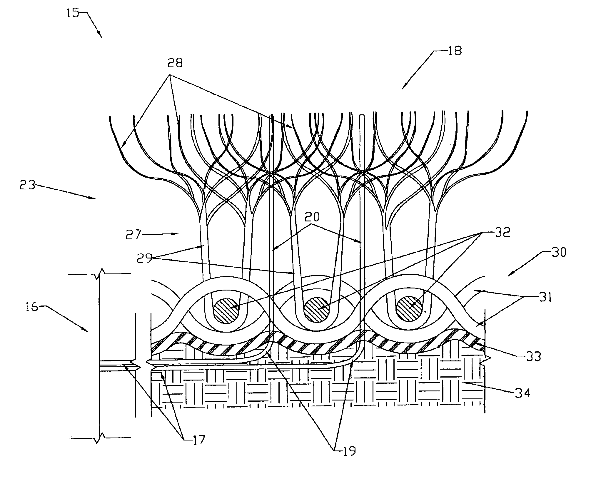
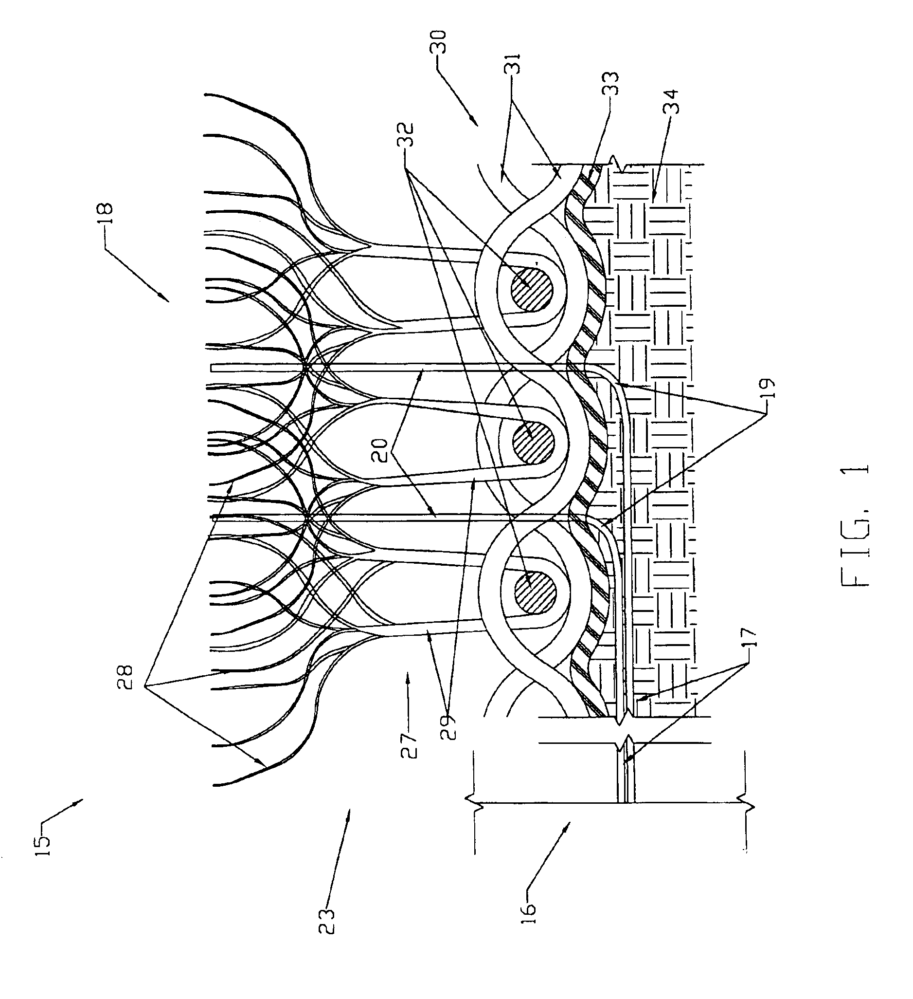
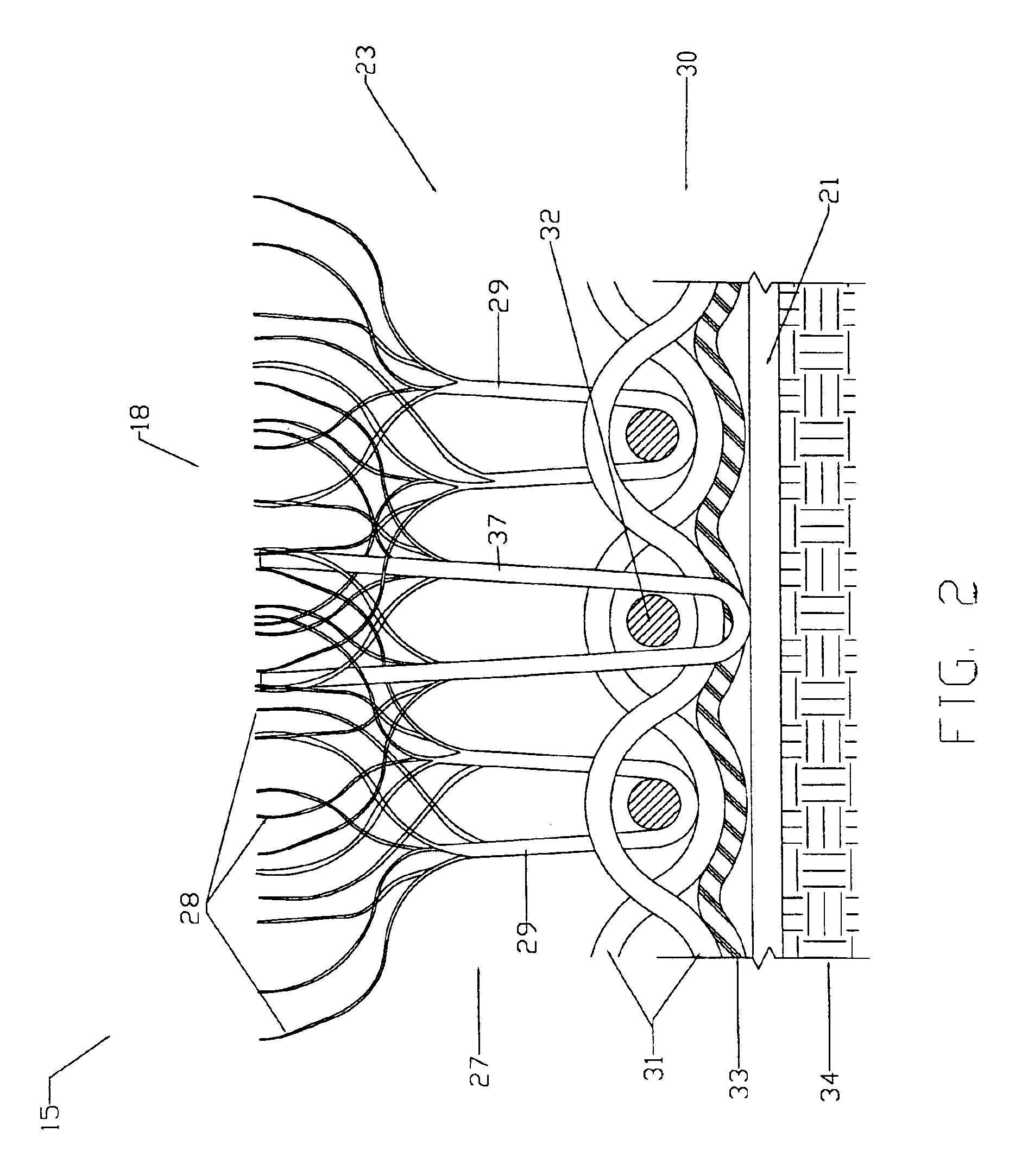
[0061]FIG. 2 shows the optically marked surface. The embodiment shown in FIG. 2 includes an artificial turfsystem 23 having artificial turf fibers 27, a primary backing layer 30, and secondary backing layer 33 supported by a base layer 34. This embodiment also includes a light source (not shown) and optical material 19. However, in this embodiment optical material 19 comprises a fiber optic strip 21 and fiber optic filaments 37. Rather than conveyance portion 17 linking light source 16 and filament portion 20, a fiber optic strip 21 is inserted horizontally between base layer 34 and secondary backing 33. Fiber optic strip 21 is a conventional flexible translucent side emitting fiber optic strip and may be side-emitting plastic, side-emitting rubber, or side-emitting glass. The PolyGlo side emitting polymer optical strip manufactured by Poly-Optical Products Inc. of 17475 Gillette Avenue, Irvine, Calif. 92614-5633 may be employed in this preferred embodiment.
[0062]As shown in FIG. 2...
seventh embodiment
[0067]FIG. 7 shows the optically marked system. In this embodiment, surface 18 is composed of a concrete layer 26. As shown in FIG. 7, concrete layer 26 is supported by an aggregate base 45 which, in turn, is supported by base layer 46. Optical filaments 47 extend horizontally through aggregate base 45 before bending to extend vertically through concrete layer 26. As shown, end portions 48 of filaments 47 protrude slightly above the top of layer 26 and when illuminated are visible on surface 18 even if layer 26 is not opaque. While this embodiment disclose the use of concrete as first layer 26, it may be readily appreciated that other types of surfacing layers may be used without departing from the invention. For example, other surfaces such as ice, wood, tile, asphalt, or rubber may be used instead of concrete.
[0068]Although not shown in the drawings, an eighth embodiment may be employed in which, rather than using fiber optic filaments 37 in conjunction with fiber optic strip 21 a...
PUM
Abstract
Turf comprising artificial or natural turf fibers and fiber optic filaments extending between the turf fibers. The present invention also provides a method of marking a surface comprising the steps of providing a light source, providing a surface to be marked, providing an optical material capable of illumination by the light source, configuring and arranging the optical material, the surface, and the light source such that illumination of the optical material is visible on the surface, and illuminating the optical material. The present invention also provides a method of manufacturing turf comprising the steps of providing a turf surface, providing optical material capable of illumination by a light source, and threading the turf surface with the optical material whereby illumination of the optical material is visible on the surface. The present invention also provides a method of manufacturing a surface comprising the steps of providing an optical material, providing a surface, arranging the optical material such that it extends above the surface, and trimming the optical material such that it is flush with the surface.
Description
[0001]This is application is a divisional of application(s) application Ser. No. 09 / 844,237 filed on Apr. 25, 2001 now U.S. Pat. No. 6,672,749.TECHNICAL FIELD[0002]The present invention relates generally to marked surfacing and, more particularly, to an improved playing surface with optical material which may be illuminated to indicate various markings, such as lines, symbols, emblems, designs or advertising, on the playing surface of sports and athletic facilities.BACKGROUND ART[0003]A variety of methods have been used in the past to mark the playing surface of sporting events. Different sports require different line markings, team logos, symbols or emblems, and advertising. Such line markings can include, but are not limited to, end zone lines, goal lines, yardage marker lines, boundary lines, creases, midfield lines, base lines, service lines, free throw lines, and circles.[0004]For surfaces such as ice, concrete, or wood, a variety of marking methods have been employed in the pr...
Claims
Application Information
Patent Timeline
Application Date:The date an application was filed.
Publication Date:The date a patent or application was officially published.
First Publication Date:The earliest publication date of a patent with the same application number.
Issue Date:Publication date of the patent grant document.
PCT Entry Date:The Entry date of PCT National Phase.
Estimated Expiry Date:The statutory expiry date of a patent right according to the Patent Law, and it is the longest term of protection that the patent right can achieve without the termination of the patent right due to other reasons(Term extension factor has been taken into account ).
Invalid Date:Actual expiry date is based on effective date or publication date of legal transaction data of invalid patent.