
System and method for offloading a computational service on a point-to-point communication link

Inactive Publication Date: 2005-09-27
HEWLETT PACKARD DEV CO LP
View PDF8 Cites 58 Cited by
  • Summary
  • Abstract
  • Description
  • Claims
  • Application Information

AI Technical Summary

Benefits of technology

[0015]In accordance with preferred embodiments of the present invention, some of t

Problems solved by technology

Therefore, due to the limited bit rate, the telephone dial-up connections that are tunneled from a remote client to a tunnel endpoint typically suffer on the performance throughput.
However, compressing and decompressing data for many tunnel connections on the tunnel endpoint presents a heavy computational load that prevents the tunnel endpoint from supporting a large number of tunnel connections.
As is also known in the art, Layer 2 point-to-point data transport typically uses an unreliable communication mechanism, e.g. UDP, and does not guarantee a reliable sequenced delivery of packets.
Further, since the Layer 2 point-to-point assumes a sequence in data delivery, out of sequence packets and packets lost during transmission adversely affect the compression and encryption mechanism.
Thus, compressing packets at a tunnel endpoint does not result in a good point-to-point compression performance.
Due to these reasons, the tunnel endpoints typically reject user requests to perform the point-to-point compression and encryption and, consequently, the end user connections suffer low-level throughputs.

Method used


Image

  • System and method for offloading a computational service on a point-to-point communication link
  • System and method for offloading a computational service on a point-to-point communication link
  • System and method for offloading a computational service on a point-to-point communication link

Examples


Embodiment Construction

[0029]The present invention is directed toward a system and method for offloading at least one computational service on point-to-point connections.

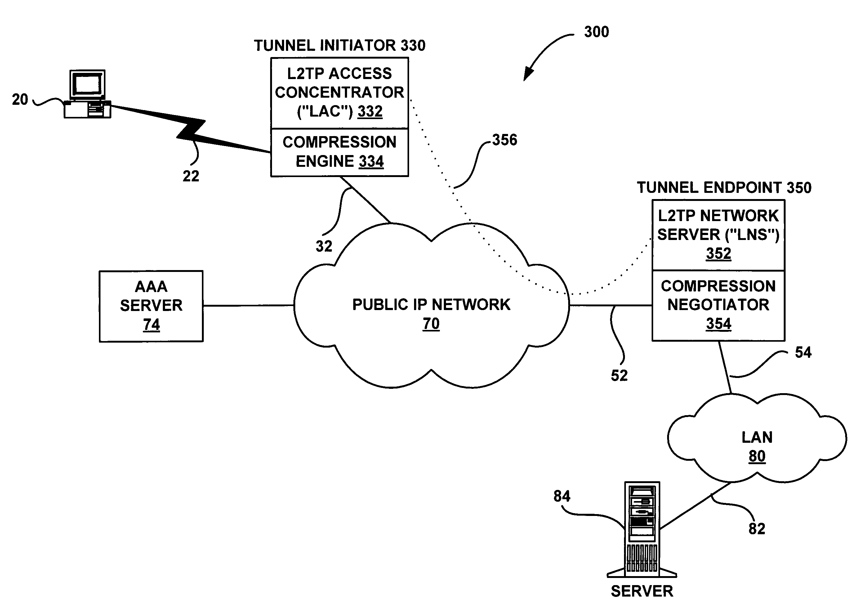
[0030]FIG. 3 is a functional block diagram illustrating an exemplary embodiment suitable for application of the present invention of network architecture 300 for offloading at least one computational service on a point-to-point connection. FIG. 3, as well as the remaining figures, will be described in reference to two exemplary computationally intensive services, a compression service and an encryption service. However, it should be understood that the system and methods described hereinafter are not limited to such computational services, and could be applied for other computational services. Further, FIG. 3, as well as the remaining figures, will be described in reference to one example of the point-to-point connection, a tunnel connection. However, it should be understood that the present invention is not limited to that particular poi...


PUM


Abstract

A system and method are shown for offloading a computational service on a point-to-point connection. When a tunnel initiator network device, such as a Level 2 Tunneling Protocol Access Concentrator (LAC), detects a tunnel client network device, the LAC sets up a tunnel connection with a tunnel endpoint network device, such a Level 2 Tunneling Protocol Network Server (LNS). During a process of establishing a call session on the tunnel connection, the LAC sends its compression capabilities to the LNS. When the LNS detects that the LAC is capable of compressing tunnel packets, the LNS negotiates compression parameters with the tunnel client network device. Subsequently, the LNS transmits the negotiated compression parameters to the LAC that configures a compression engine based on the received compression parameters. Hereinafter, the tunnel client network device will send compressed tunnel packets to the LAC that will decompress the received tunnel packets prior to transmitting the tunnel packets to the LNS on the tunnel connections. Similarly, the LNS will send uncompressed tunnel packets on the tunnel connection to the LAC that will compress the received tunnel packets prior to transmitting the tunnel packets to the tunnel client network device.

Description

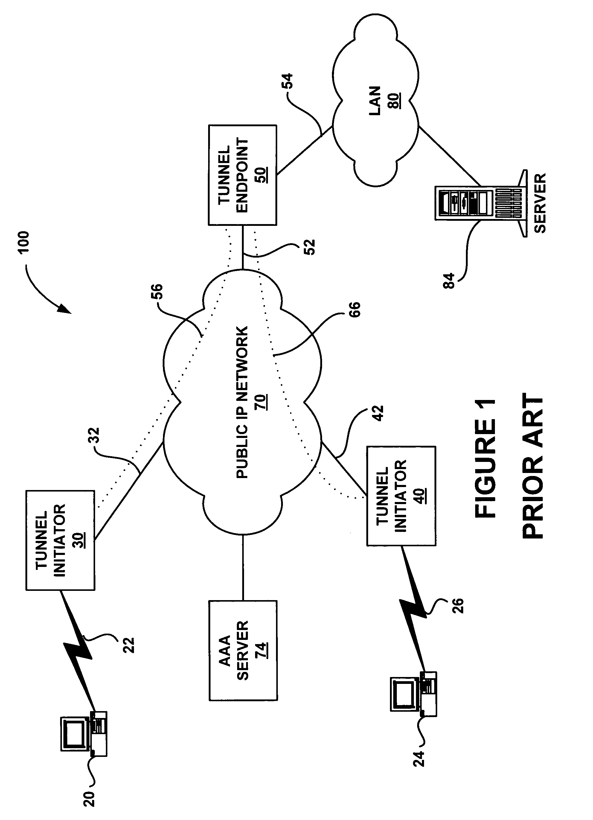
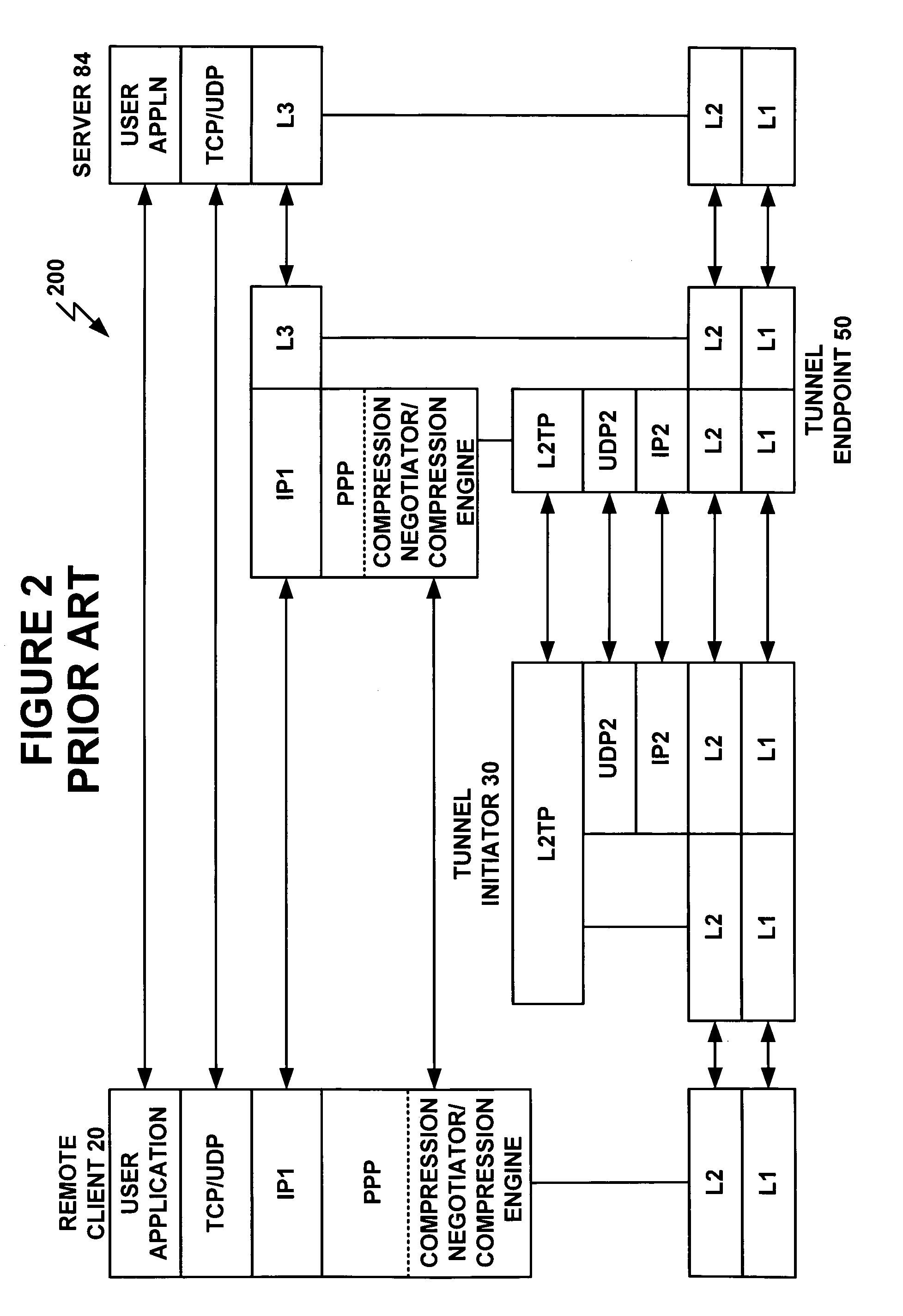
FIELD OF INVENTION[0001]The present invention relates to data communications. More specifically, it relates to computational service offloading, such as compression and encryption offloading, across point-to-point communication links.BACKGROUND OF THE INVENTION[0002]Connection oriented point-to-point communication links, such as a Layer 2 Tunneling Protocol (L2TP) tunnel, are an increasingly common feature of network infrastructures. Tunnels are prearranged connections established by agreement between internet service providers (ISPs). See Request for Comment (RFC) 2661 and Layer Two Tunnelling Protocol (L2TP), A. Valencia, et al., draft-ietf-pppext-l2tp-16.txt, June 1999, herein incorporated by reference, available from the Internet Engineering Task Force (IETF) website.[0003]FIG. 1 shows an architecture 100 involving an internet protocol (IP) network 70 to which a tunnel initiator 30 is linked via a network connection 32, a tunnel initiator 40 is linked via a network connection 42...

Claims


Application Information

Patent Timeline
IPC IPC(8): G06F15/177G06F15/16H04L29/06
CPCH04L67/14H04L69/24
Inventor PUTHIYANDYIL, SANIL KUMARSENTHILNATHAN, JANAKIRAMANRAMANKUTTY, RAJESHRADHAKRISHNAN, SHAJI
Owner HEWLETT PACKARD DEV CO LP
Learn More