Fuel vapor processing system

a technology of fuel vapor and processing system, which is applied in the direction of combustion air/fuel air treatment, functional valve types, machines/engines, etc., can solve the problems of fuel spillage, and achieve the effect of compact structur

Inactive Publication Date: 2005-10-04
HONDA MOTOR CO LTD
View PDF6 Cites 30 Cited by
  • Summary
  • Abstract
  • Description
  • Claims
  • Application Information

AI Technical Summary

Benefits of technology

[0012]Thus, the check valve operates in two stages so that the internal pressure of the fuel tank can be favorably controlled by the opening of the low set-pressure valve when the fuel tank is being filled to full so that the sensor associated with the fill nozzle can successfully detect a tank full state, and any excessive rise in the internal pressure of the fuel tank typically caused by a high temperature of the surrounding environment can be avoided by the opening of the high set-pressure valve. Therefore, the present invention can prevent the spilling of fuel that could be otherwise caused by the failure of the sensor to detect a tank full state, and releasing of fuel vapor from the fill pipe and excessive rise in the internal pressure of the fuel tank that could be otherwise cause by the failure of the check valve to conduct the fuel vapor to the canister at an adequate flow rate.
[0013]The low set-pressure valve and high set-pressure valve may be disposed either coaxially to each other or laterally one next to the other. According to a preferred embodiment of the present invention, each of the low set-pressure valve and high set-pressure valve is provided with a valve chamber communicating with a canister end of the corresponding passage, a port communicating with a fuel tank end of the corresponding passage, a valve member adapted to selectively close the port, and a spring member resiliently urging the valve member against the port. A highly compact structure can be achieved when the valve member of the high set-pressure valve is cup-shaped, and defines the port of the low set-pressure valve in a bottom wall thereof, and the valve member and spring member of the low set-pressure valve is received inside the valve member of the high set-pressure valve.

Problems solved by technology

Such a delay in detecting the tank full state may lead to spilling fuel.

Method used


Image

  • Fuel vapor processing system
  • Fuel vapor processing system
  • Fuel vapor processing system

Examples


Embodiment Construction

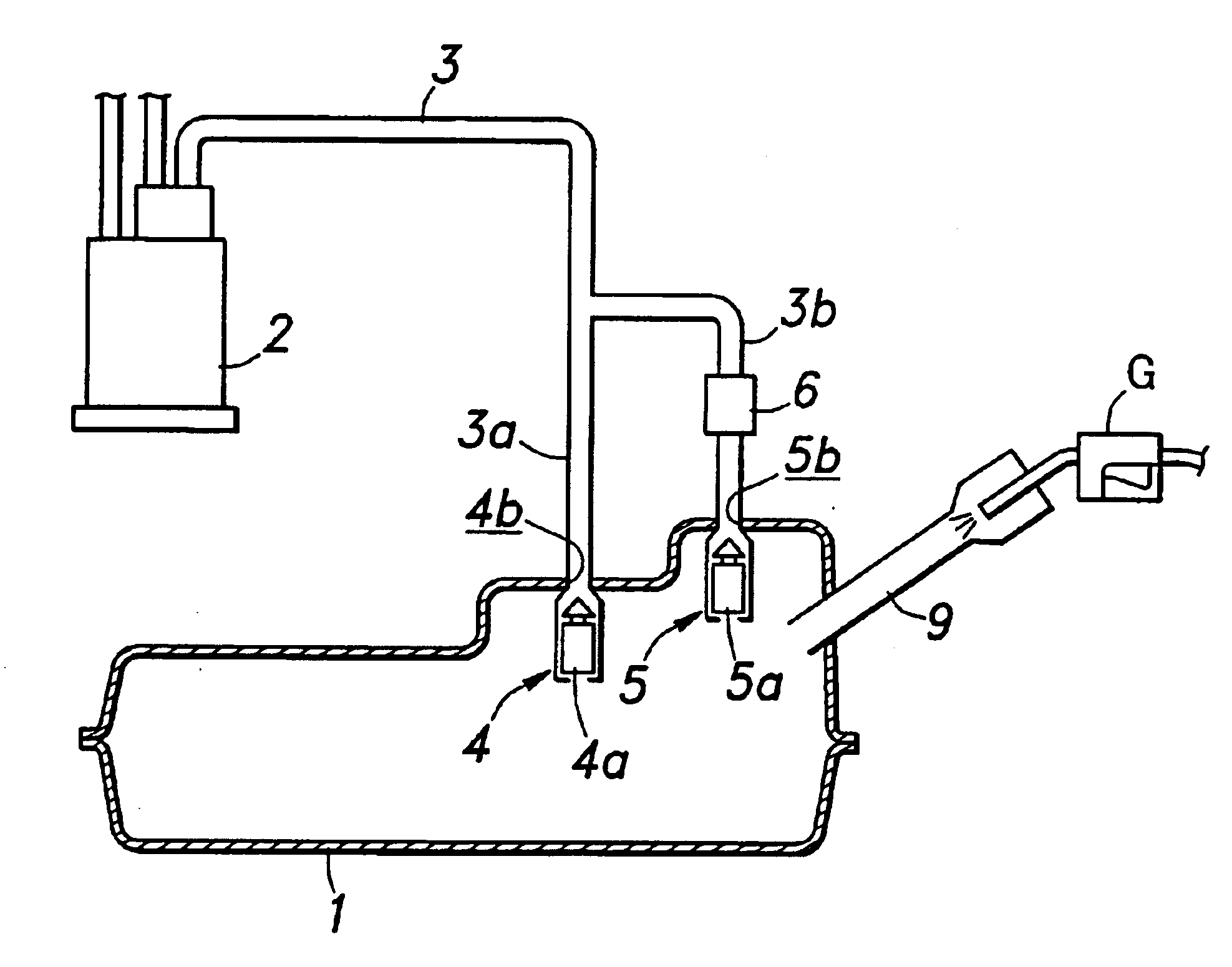
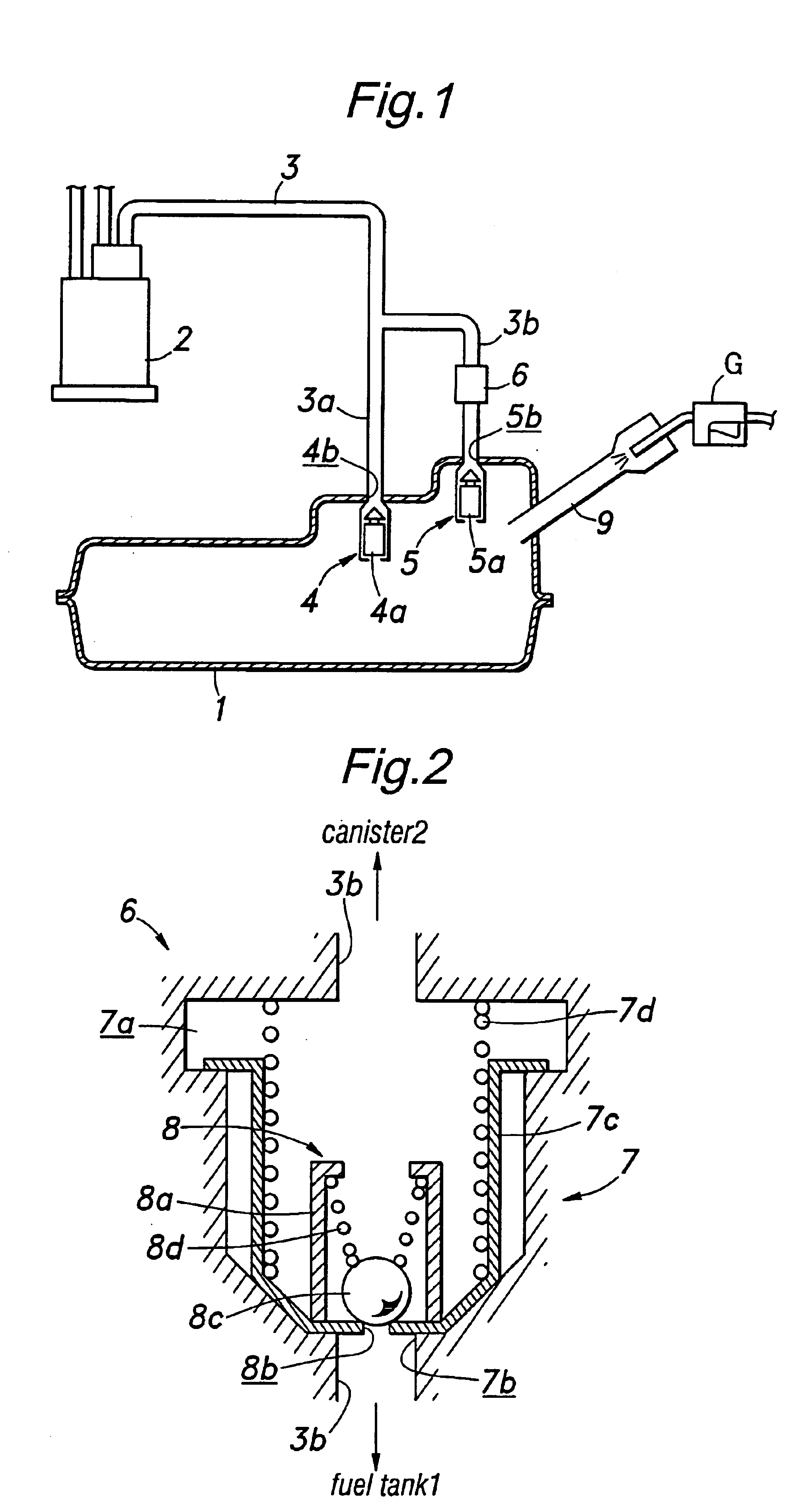
[0022]FIG. 1 is a diagram showing an overall structure of the fuel vapor processing system embodying the present invention, in which the parts corresponding to those of the prior art shown in FIG. 6 are denoted with like numerals without repeating the description of such parts. Referring to FIG. 1, a fuel tank 1 and a canister 2 are connected to each other via a fuel vapor passage 3, which is branched into a pair of branch passages 3a and 3b at the end communicating with the fuel tank 1. The first branch passage 3a is selectively closed by a float valve 4 provided at the fuel tank end of the first branch passage 3a, and the second branch passage 3b is selectively closed by a cut valve 5 provided at the fuel tank end of the second branch passage 3b.

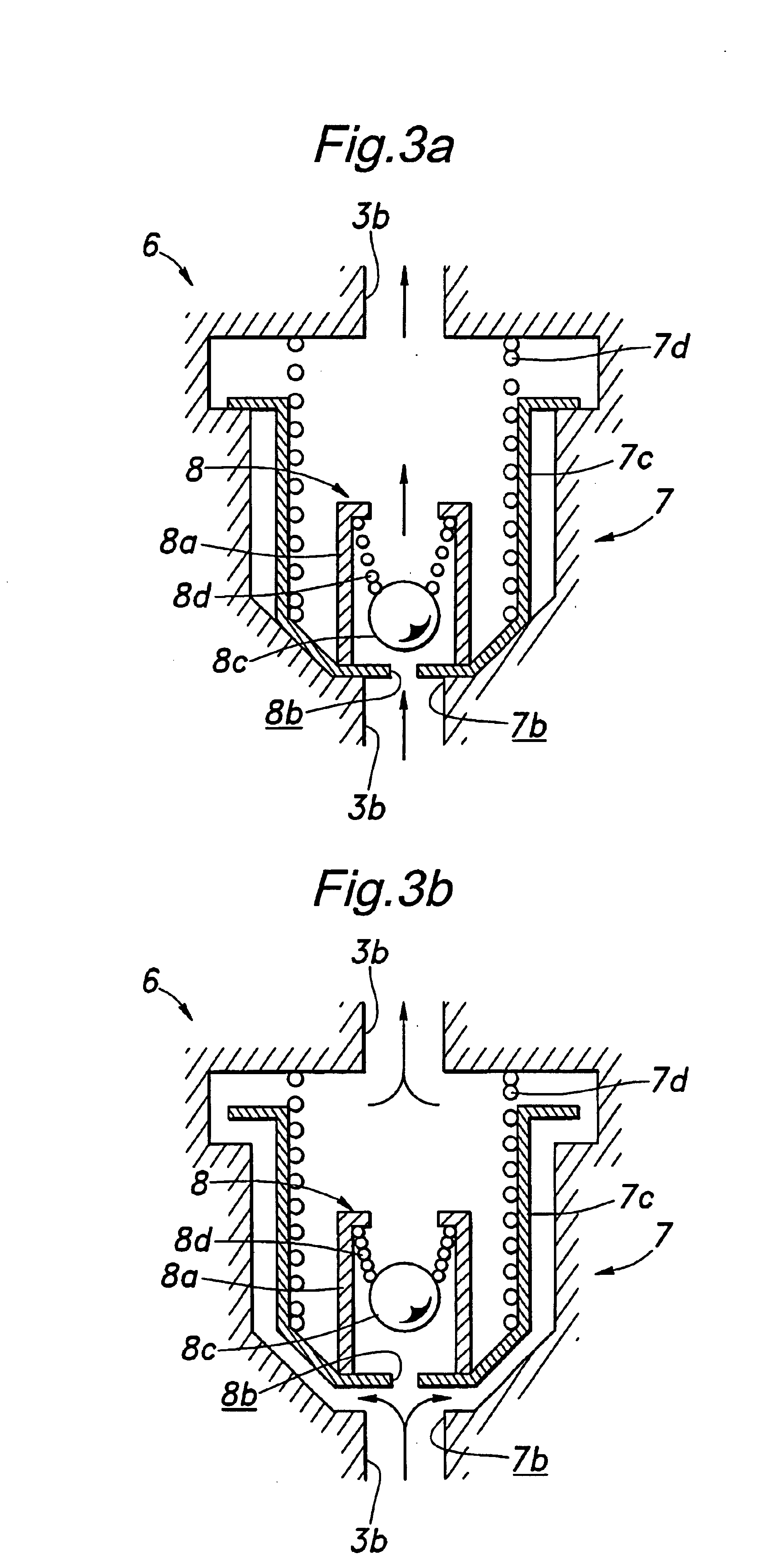
[0023]An intermediate part of the second branch passage 3b is provided with a two-stage check valve 6 which comprises a high set-pressure valve 7 and a low set-pressure valve 8 incorporated in the high set-pressure valve 7 as shown in FIG...


PUM


Abstract

In a fuel vapor processing system, a float valve and a check valve are provided in upper parts of a fuel tank to conduct fuel vapor to a canister via a fuel vapor passage. The check valve includes a low set-pressure valve and high set-pressure valve, and operates in two stages so that the internal pressure of the fuel tank can be favorably controlled by the opening of the low set-pressure valve when the fuel tank is being filled to full so that the sensor associated with the fill nozzle can successfully detect a tank full state, and any excessive rise in the internal pressure of the fuel tank typically caused by a high temperature of the surrounding environment can be avoided by the opening of the high set-pressure valve.

Description

TECHNICAL FIELD[0001]The present invention relates to a fuel vapor processing system that processes fuel vapor produced in a fuel tank by forwarding it to a canister.BACKGROUND OF THE INVENTION[0002]A conventional fuel vapor processing system for processing fuel vapor produced from an automotive fuel tank is illustrated in FIG. 6, Such a system is disclosed for instance in Japanese patent application No. 2002-57054. In this system, an upper part of a fuel tank 1 communicates with a canister 2 via a fuel vapor passage 3. In this case, the upper part of the fuel tank 1 consists of two levels. The fuel tank end of the fuel vapor passage 3 is branched into a first branch passage 3a that communicates with the lower level of the fuel tank upper part and a second branch passage 3b that communicates with the upper level of the fuel tank upper part. The lower level of the fuel tank upper part is provided with a float valve 4 that communicates with the first branch passage 3a, and the upper l...

Claims


Application Information

Patent Timeline
Patent Type & Authority Patents(United States)
IPC IPC(8): F02M25/08F02M37/00
CPCF02M25/0836Y10T137/7841Y10T137/86324
Inventor YANASE, TAIKIGOUMA, HISAYUKI
Owner HONDA MOTOR CO LTD
Why Eureka
Try Eureka