Variable geometry turbocharger

a turbocharger and variable geometry technology, applied in the field of turbochargers, can solve the problems of increasing manufacturing costs, limiting flexibility in turbine housing design and structure, and creating maintenance problems

Inactive Publication Date: 2005-10-04
GARRETT TRANSPORATION I INC
View PDF20 Cites 75 Cited by
  • Summary
  • Abstract
  • Description
  • Claims
  • Application Information

AI Technical Summary

Problems solved by technology

While multiple vane variable nozzle turbochargers have significantly increased the overall efficiency and capability of turbochargers, the complexity of support and actuation structures for the vanes have increased manufacturing costs and occasionally created mainte...

Method used


Image

  • Variable geometry turbocharger
  • Variable geometry turbocharger
  • Variable geometry turbocharger

Examples


Embodiment Construction

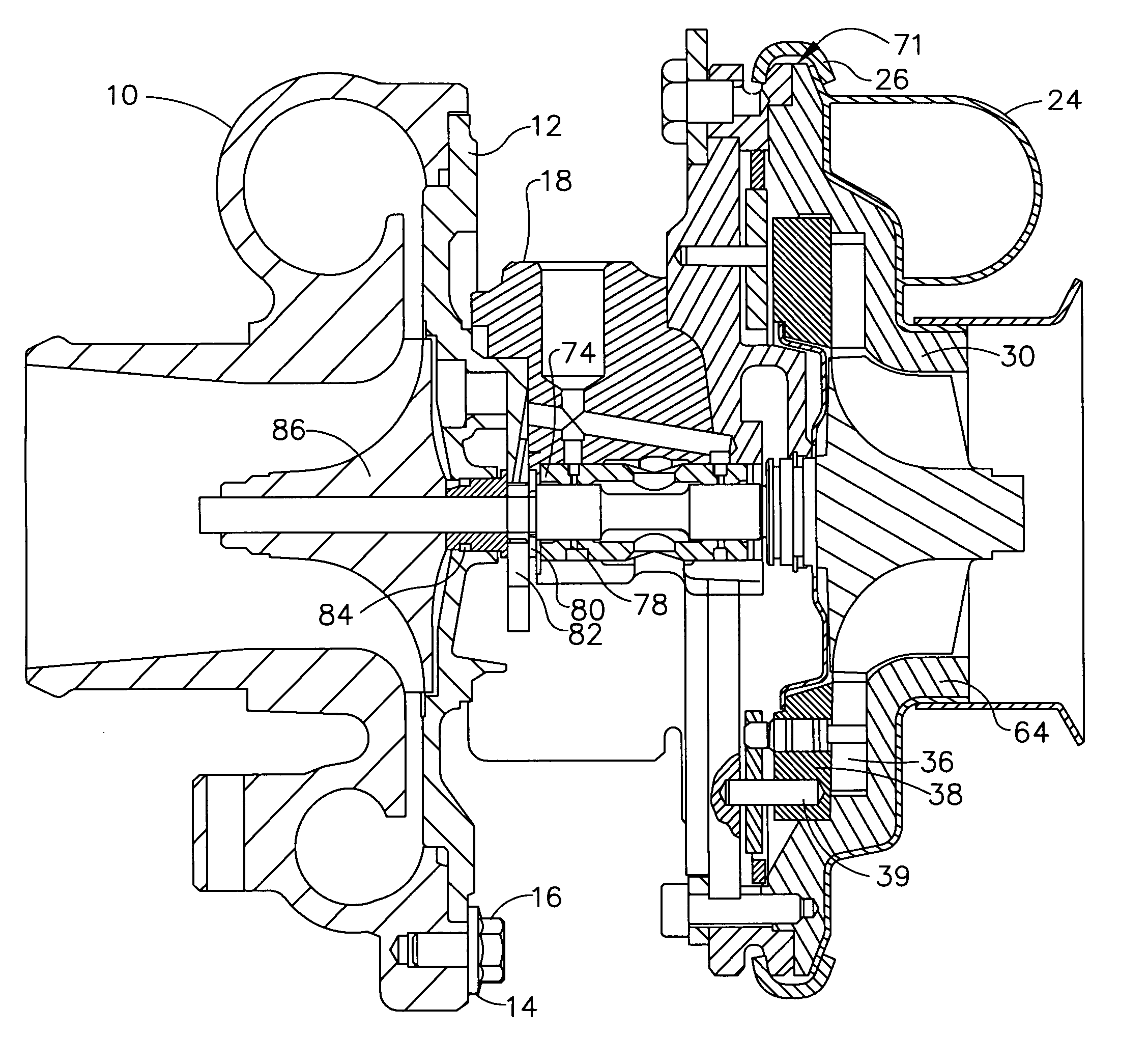
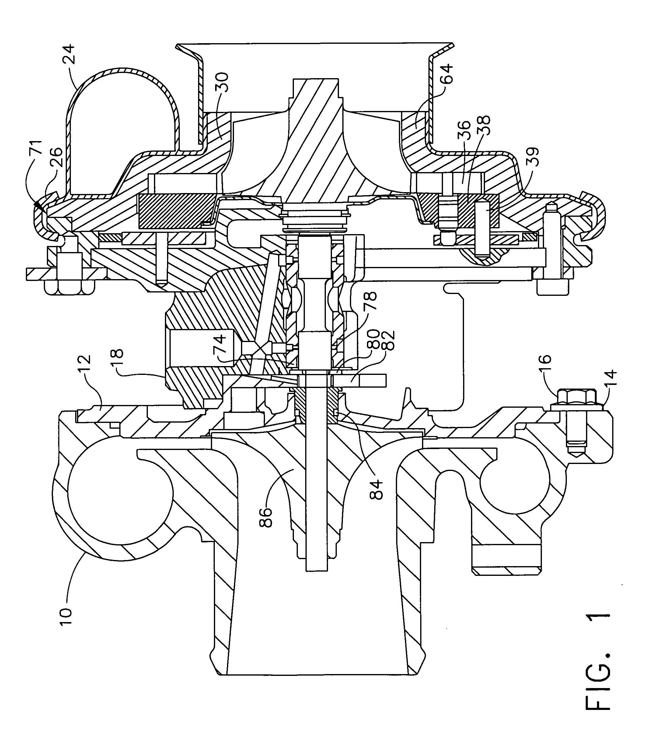
[0017]Referring to the drawings, the embodiment of the invention shown in FIG. 1 includes a compressor housing 10 which is connected to a backplate 12 using two or more clamps 14 secured by bolts 16. The backplate is attached to a centre housing 18 with multiple bolts 20 and a seal ring 22. For the embodiment shown a sheet metal exhaust housing 24 is connected to the centre housing using bands 26 secured by bolts 28. Exhaust gas or other high energy gas supplying the turbocharger enters the exhaust housing through inlet 32.

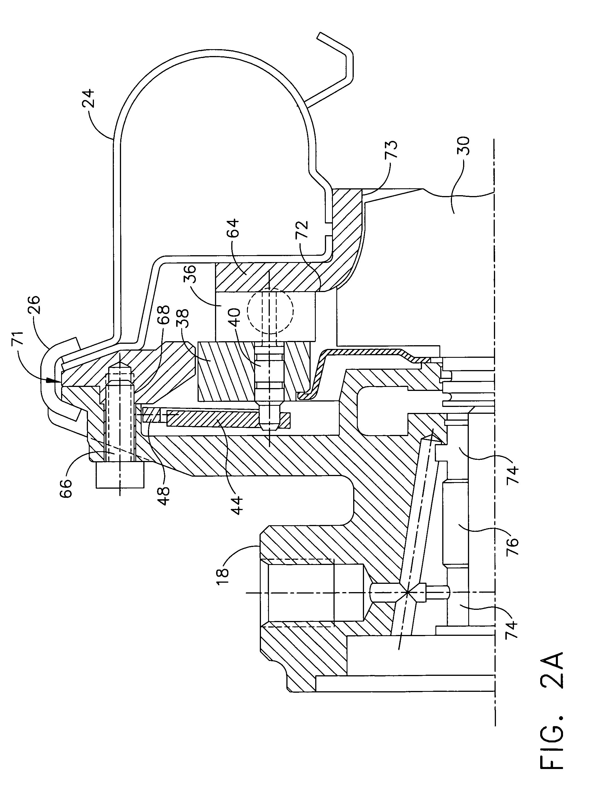
[0018]As best seen in FIGS. 2a, 2b, 3 and 4, a cartridge, generally designated 34 is mounted to the centre housing. A turbine wheel and shaft assembly 30 is carried by the bearings with the turbine wheel suspended within the cartridge. Multiple vanes 36 are mounted to a cartridge base 38. The vanes pivot on posts 40 extending from the vanes into holes 42 in a surface 43 on the base which forms the inner inlet nozzle wall. Actuation arms 44 extend from the vane pos...


PUM


Abstract

A cartridge is formed by an insert fixed to a base to form turbine intake nozzles in which vanes are rotatably mounted, and the base is fixed to a center housing. A separate exhaust housing which is formed from sheet metal is fixed to the cartridge outside of the insert in order to provide an intake and an outlet for exhaust gases driving a turbine wheel on a shaft journaled in the center housing.

Description

BACKGROUND OF THE INVENTION[0001]1. Field of the Invention[0002]This invention relates generally to the field of turbochargers having variable turbine inlet geometries. More particularly, the present invention provides a structural arrangement for variable inlet vane support independent of the turbine housing.[0003]2. Description of the Related Art[0004]In a turbocharger it is often desirable to control the flow of exhaust gas into the turbine to improve the efficiency or operational range. Various configurations of variable nozzles have been employed to control the exhaust gas flow. Multiple pivoting vanes annularly positioned around the turbine inlet and commonly controlled to alter the throat area of the passages between the vanes is an approach which has been successfully used in prior turbochargers. Various approaches to this method for implementing a variable nozzle are disclosed in U.S. Pat. No. 4,679,984 to Swihart et al. entitled “Actuation System for Variable Nozzle Turbin...

Claims


Application Information

Patent Timeline
IPC IPC(8): F01D17/16F01D17/00F04D25/02F04D25/04F02B37/24F01D9/02
CPCF01D9/026F04D25/04F01D17/165F05D2220/40F02B39/00
Inventor FIGURA, GIORGIOJECKEL, DENISDECHANET, ERIC
Owner GARRETT TRANSPORATION I INC
Why Eureka
Try Eureka