Spin-on desiccant cartridge with integral oil removal filter

a technology of desiccant cartridge and oil removal filter, which is applied in the direction of filtration separation, auxillary pretreatment, separation process, etc., can solve the problems of difficult to contain the oil in the compressor, interfere with the optimal operation of the system, and reduce the efficiency of the compressor, so as to achieve the effect of simple and economical manner

Inactive Publication Date: 2005-10-04
BENDIX COMML VEHICLE SYST LLC
View PDF36 Cites 32 Cited by
  • Summary
  • Abstract
  • Description
  • Claims
  • Application Information

AI Technical Summary

Benefits of technology

[0008]An improved air dryer assembly for removing moisture and oil from a compressed air system is provided that meets the above needs and others in a simple and economical manner.

Problems solved by technology

Water, particulates, and oil in the compressed air system can lead to component degradation and interfere with optimal operation of the system.
As will be appreciated, it is difficult to contain the oil in the compressor and oil occasionally becomes entrained in the pressurized air stream exiting the compressor.
Periodic replacement of the desiccant material is desirable since, in use, the desiccant material becomes coated with contaminants such as oil, which ultimately reduces its water vapor retention characteristics.
Unfortunately, known designs have not adequately addressed removal of coalesced oil from the cartridge.
However, a poor design can lead to desiccant leakage, to a reduction in the removal of oil from the cartridge, thus leading to a decrease in desiccant life, and ultimately to a negative impact on the performance of the compressed air system.

Method used


Image

  • Spin-on desiccant cartridge with integral oil removal filter
  • Spin-on desiccant cartridge with integral oil removal filter
  • Spin-on desiccant cartridge with integral oil removal filter

Examples


Embodiment Construction

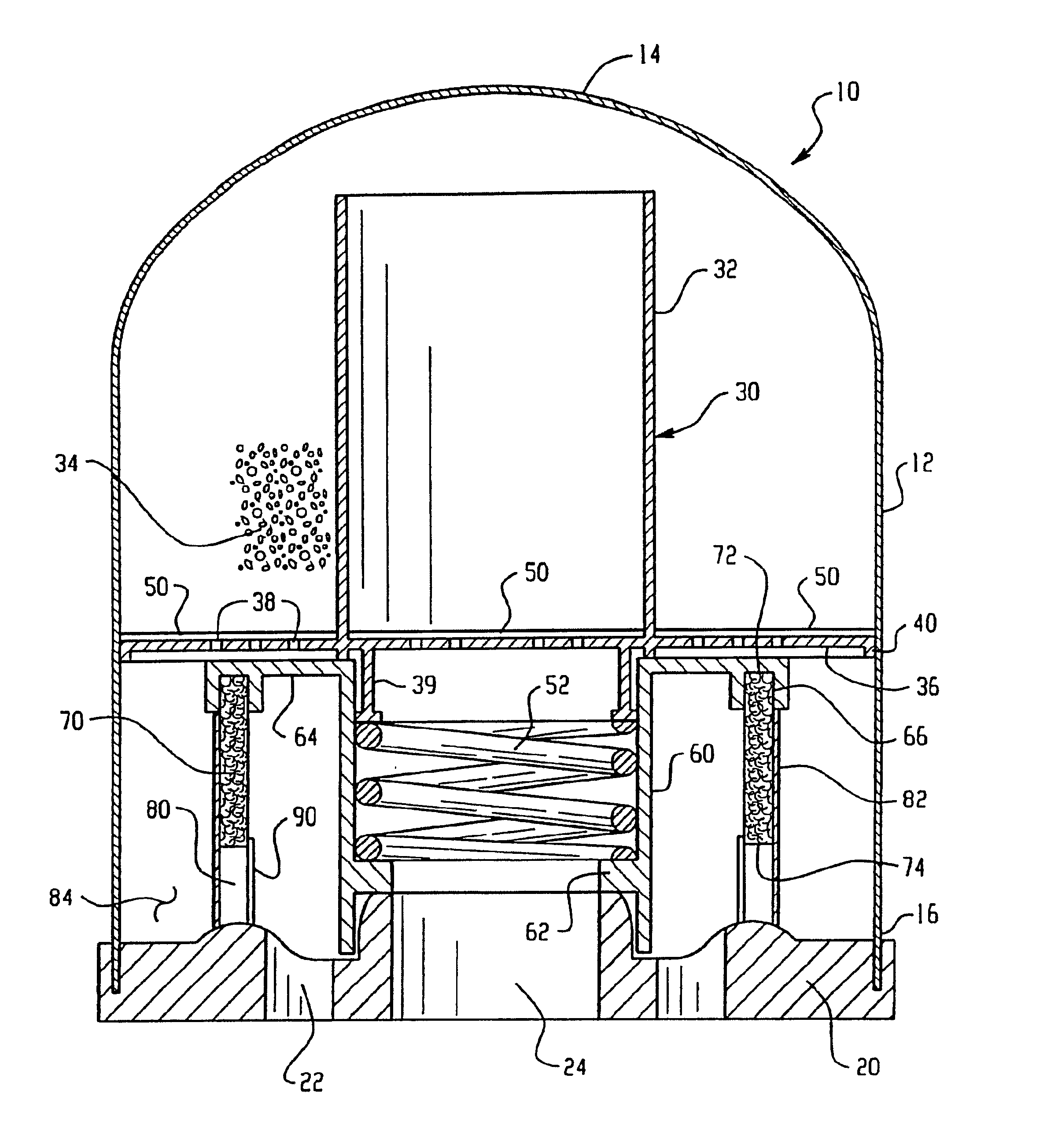
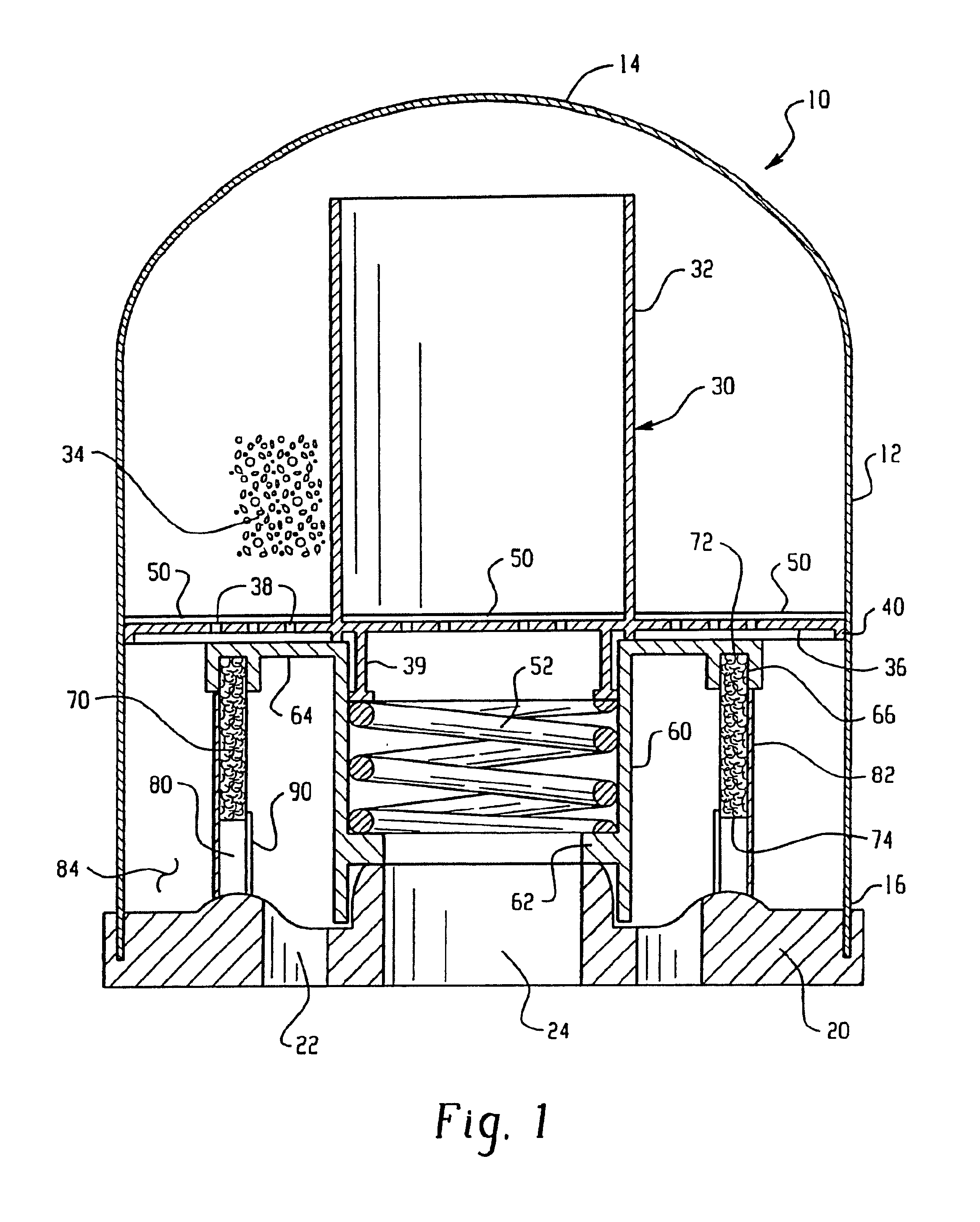
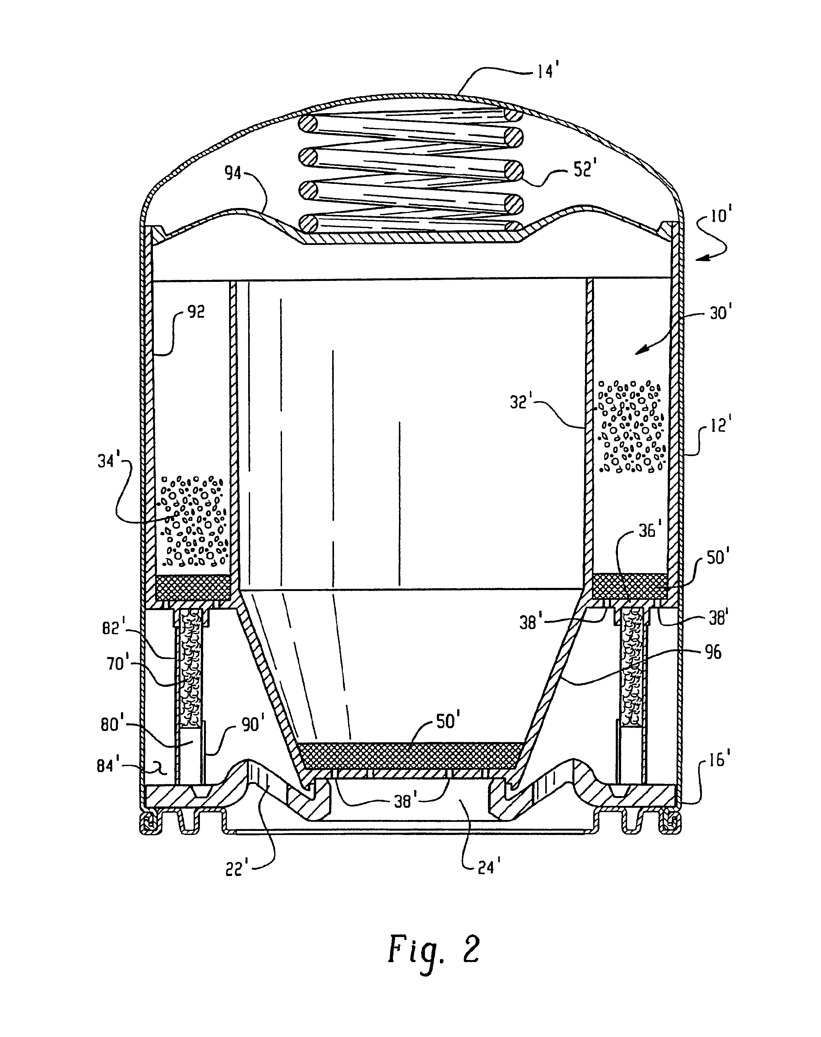
[0017]An air dryer formed in accordance with the present invention is shown in FIG. 1 and is generally designated by reference numeral 10. It will be appreciated that other components of the air dryer assembly are generally well known in the art, for example as shown and described in U.S. Pat. No. 5,622,544, the disclosure of which are incorporated herein by reference, so that further discussion herein is deemed unnecessary. The spin-on cartridge of the present invention includes a first or outer shell 12 that is preferably cup-shaped. That is, a first or closed end 14 forms a dome while a second or open end 16 is sealingly secured to a load plate 20. The load plate includes an inlet 22 that allows pressurized air from a compressor (not shown) to pass through the cartridge where contaminants and moisture are removed from the air stream. A second passage or outlet 24 is also formed in the load plate 20 and in one embodiment is located at a central location. The outlet 24 communicates...


PUM

PropertyMeasurementUnit
compacting forceaaaaaaaaaa
pressureaaaaaaaaaa
desiccantaaaaaaaaaa

Abstract

An air dryer assembly for removing moisture and oil from a compressed air system includes a desiccant material received in a shell for adsorbing moisture as compressed air passes therethrough. A coalescing element is disposed between an inlet and outlet for removing oil aerosols from the compressed air. A check valve is disposed in parallel with the coalescing element and forces the compressed air to pass through the coalescing element as air flows from the inlet to the outlet. During a purge or reverse flow, compressed air bypasses the coalescing element and removes oil collected in the cartridge through the inlet.

Description

CROSS REFERENCE TO RELATED APPLICATIONS[0001]This application is a continuation of U.S. patent application Ser. No. 10 / 205,795 filed Jul. 26, 2002, now U.S. Pat. No. 6,786,953 issued Sep. 7, 2004, the entire disclosure of which is hereby incorporated by reference.BACKGROUND OF INVENTION[0002]This invention relates to a compressed air system, and specifically an air dryer assembly for the compressed air system that removes moisture and oil. The invention finds particular application in a compressor system for vehicles that use pressurized air to selectively control application of vehicle brakes and for other air operated systems associated with the vehicle.[0003]Compressed air systems are used in conventional brake systems, for example, to provide and maintain air under pressure to operate vehicle brakes and auxiliary air systems. Water, particulates, and oil in the compressed air system can lead to component degradation and interfere with optimal operation of the system. Accordingly...

Claims


Application Information

Patent Timeline
Patent Type & Authority Patents(United States)
IPC IPC(8): B01D46/24B01D46/10B01D53/26
CPCB01D46/003B01D46/4272B01D53/261Y10S55/25
Inventor FORNOF, WILLIAM P.KOENIG, JAMES P.QUINN, LEONARD
Owner BENDIX COMML VEHICLE SYST LLC
Why Eureka
Try Eureka