Motor drive with voltage-accurate inverter

a technology of voltage accuracy and inverter, which is applied in the direction of electric generator control, dynamo-electric converter control, dynamo-electric gear control, etc., can solve the problems of variable delay in switching speed in the device, non-linearity of the characteristics of the switching device, and inability to accurately represent the voltage output of the input inverter signal, so as to avoid the non-linearity of the switching device and improve the voltage accuracy

Inactive Publication Date: 2005-10-04
ROCKWELL AUTOMATION TECH
View PDF5 Cites 16 Cited by
  • Summary
  • Abstract
  • Description
  • Claims
  • Application Information

AI Technical Summary

Benefits of technology

[0007]The present inventor has determined that modeling nonlinearities of the switching devices can be avoided by the introduction of a minor voltage feedback loop from the output of the inverter to its input. Although current feedback loops are known for the purpose of providing current controlled outputs for inverters, adding of a minor voltage feedback loop significantly improves voltage accuracy beyond that provided by current feedback.
[0009]Thus it is one object of the invention to provide a simple mechanism for correcting for nonlinearities in the inverter that does not require a modeling of inverter nonlinear characteristics.
[0011]Thus it is another object of the invention to provide the minor loop voltage feedback at a point of constancy in the error signal allowing improved feedback loop closure. The voltage minor loops are intentionally placed in the synchronously rotating reference frame so that PI regulators can be used to reduce the steady state errors close to zero.

Problems solved by technology

Despite the efficiency of such inverters, the voltage output of such inverters may not be an accurate representation of the input inverter signals particularly at lower voltages.
Much of this accuracy problem appears to result from a non-linearity of the characteristics of the switching devices.
For example, a variable delay in switching speed in the devices will affect the amplitude and phase of the synthesized waveform.
To the extent that such nonlinearities may vary from switching device to switching device, this approach requires a cumbersome adjustment of the model used in each inverter.

Method used


Image

  • Motor drive with voltage-accurate inverter
  • Motor drive with voltage-accurate inverter
  • Motor drive with voltage-accurate inverter

Examples


Embodiment Construction

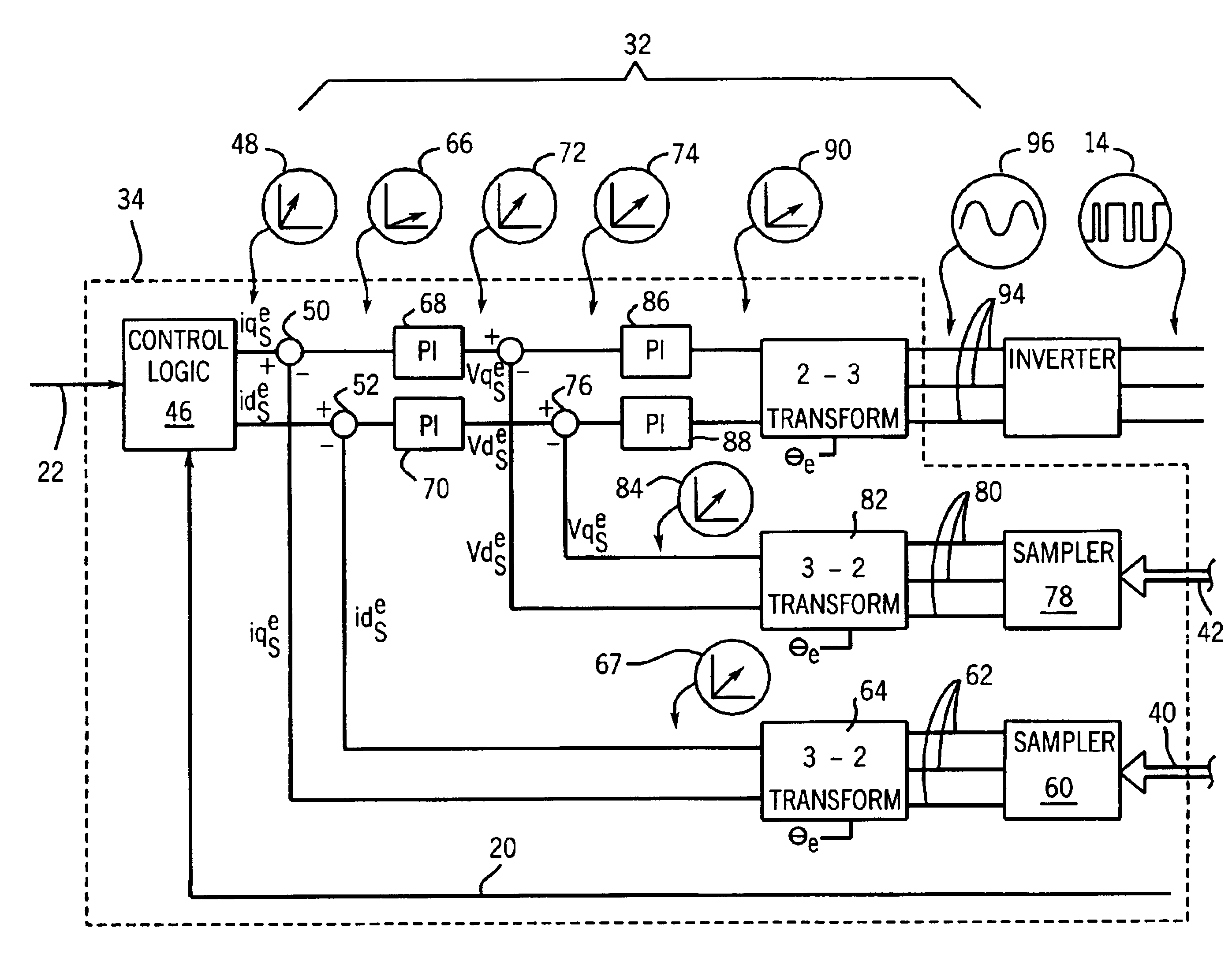
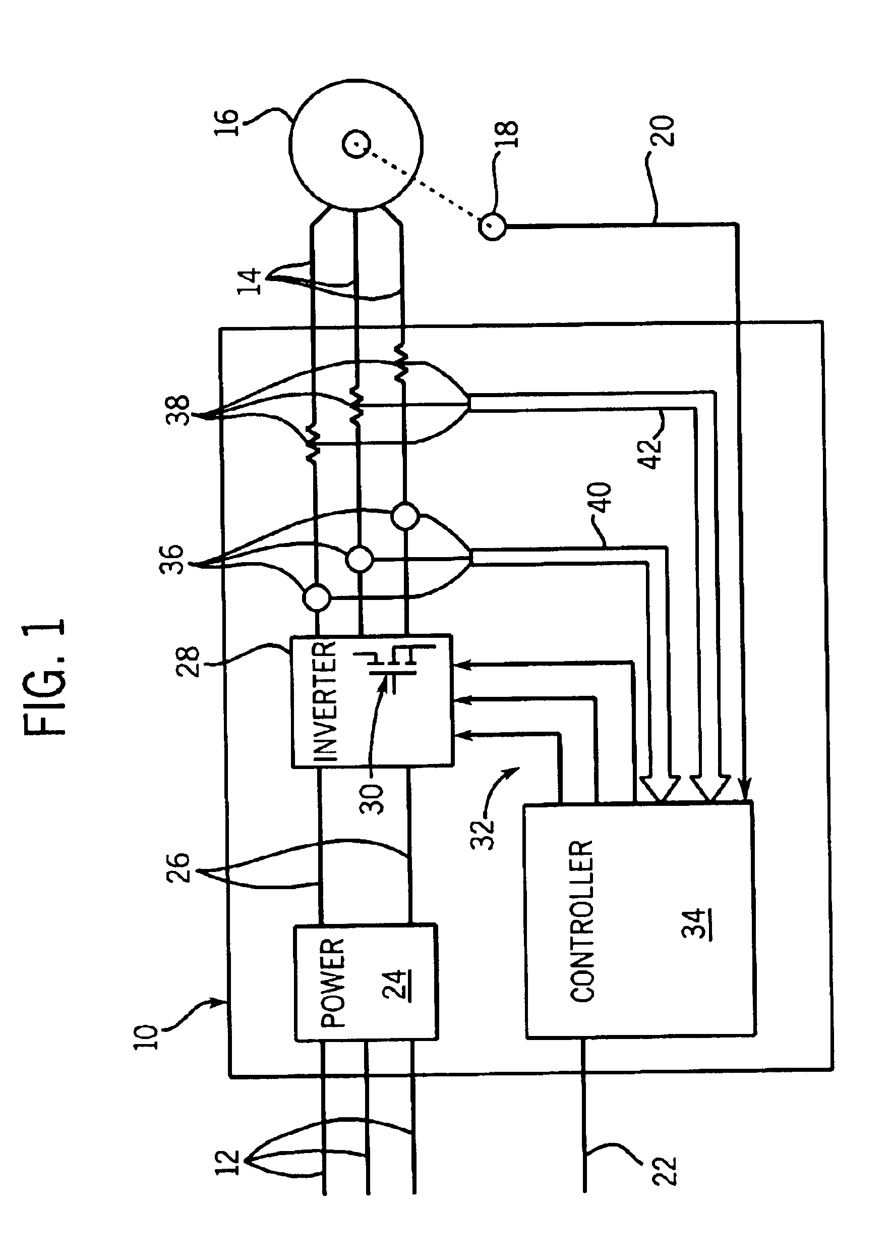
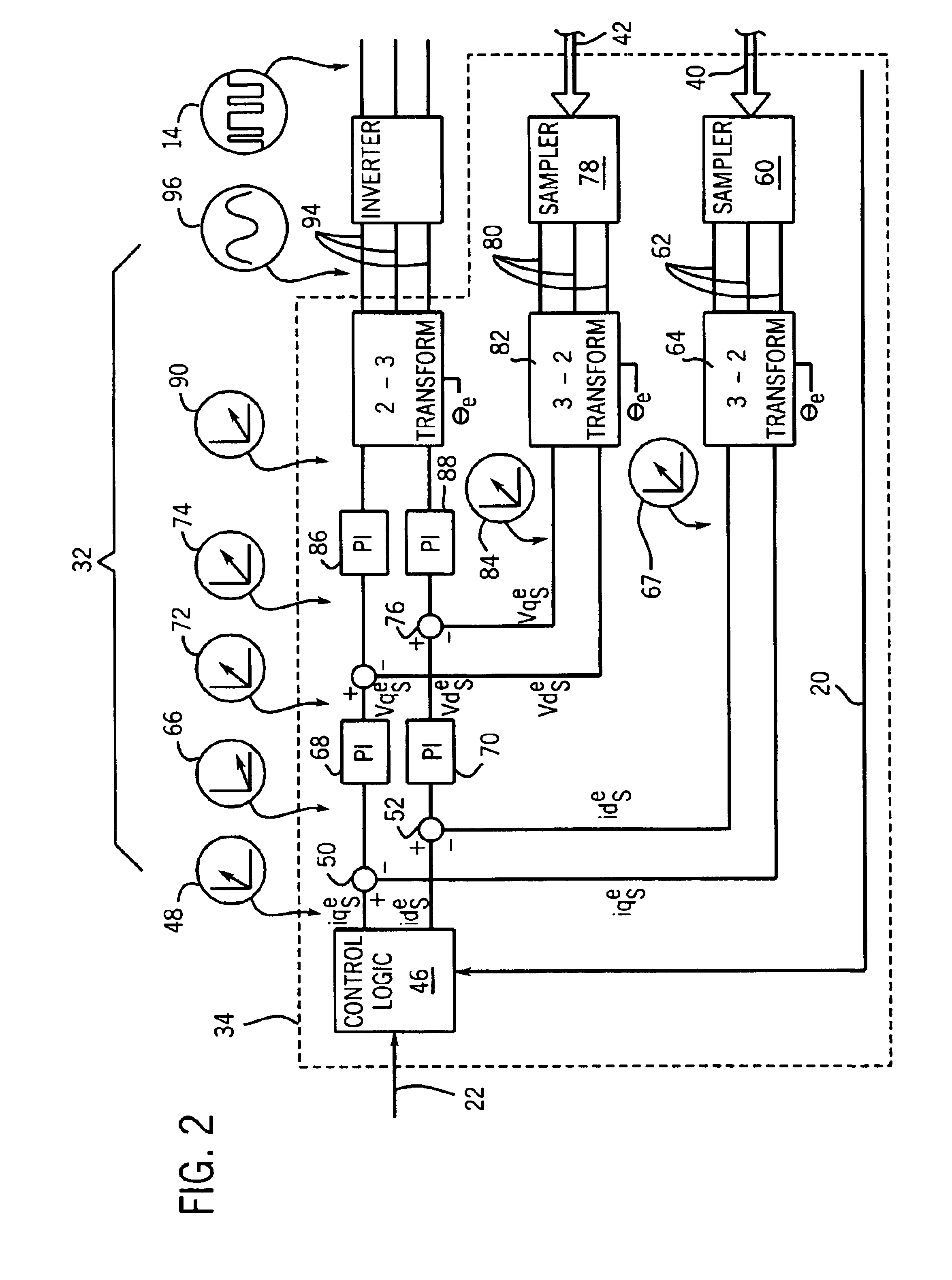
[0027]Referring now to FIG. 1, a motor drive 10 may receive a command signal 22 from a user or an external device providing a desired motor torque, motor speed, motor position or the like for control of a motor three-phase induction motor 16. The motor drive 10 accepts AC power from a three-phase line 12 and produces synthesized three-phase motor drive signals 14 for the induction motor 16 according to the command signal 22.

[0028]The three-phase line 12 is received by a power supply 24 within the motor drive 10, the power supply 24 rectifying and filtering the three-phase power of the line 12 to provide a source of DC power 26. The DC power 26 is then provided to an inverter 28 having solid state switching devices 30 (only one shown for simplicity) such as insulated gate bipolar transistors (IGBT) which modulate the DC power 26 to synthesize the three-phase motor drive signals 14 according to inverter input signals 32 received from a controller 34. Generally, the inverter input sign...


PUM


Abstract

Improved voltage stiffness in the output voltage of an inverter used for a motor drive is obtained by a minor voltage feedback loop connecting the output of the inverter to a three-phase input in a vector domain.

Description

CROSS-REFERENCE TO RELATED APPLICATIONSSTATEMENT REGARDING FEDERALLY SPONSORED RESEARCH OR DEVELOPMENTBACKGROUND OF THE INVENTION[0001]The present invention relates to motor drives and in particular to an improved inverter used in such motor drives.[0002]Motor drives are used to control the speed, torque, or other operating characteristics of AC induction motors.[0003]In a typical large motor drive, three-phase power from a power line is rectified and filtered to provide a source of DC power. The DC power is provided to an inverter which converts the DC power back again to synthesized AC power that is used to drive the motor. By changing the frequency of the synthesized AC power, the speed or torque of the induction motor may be affected.[0004]In operation, a controller within the motor drive receives a command signal from a user, for example, torque or speed, and provides the inverter with input signals indicating the desired characteristics of the synthesized AC power needed to ac...

Claims


Application Information

Patent Timeline
Patent Type & Authority Patents(United States)
CPCH02M7/53873H02P21/0035H02M2007/53876H02P21/22H02M7/53876
Inventor MATSUO, TAKAYOSHI
Owner ROCKWELL AUTOMATION TECH
Why Eureka
Try Eureka