Antenna for foldable radio device

Inactive Publication Date: 2005-10-04
CANTOR FITZGERALD SECURITIES
View PDF10 Cites 45 Cited by
  • Summary
  • Abstract
  • Description
  • Claims
  • Application Information

AI Technical Summary

Benefits of technology

[0006]An advantage of the invention is that an antenna with satisfactory electrical characteristics fits inside a foldable radio device. The antenna gain during use of the device is considerably higher than that of a PIFA of the same height, for instance. Another advantage of the invention is that antenna matching is easily arranged by providing an appropri

Problems solved by technology

Their drawback is the impracticality generally associated with a protruding structural element.
Naturally it would be possible to use internal PIFA-type planar antennas, but the thin structure of the folding parts in the mobile phone would result in the distance between

Method used


Image

  • Antenna for foldable radio device
  • Antenna for foldable radio device
  • Antenna for foldable radio device

Examples


Embodiment Construction

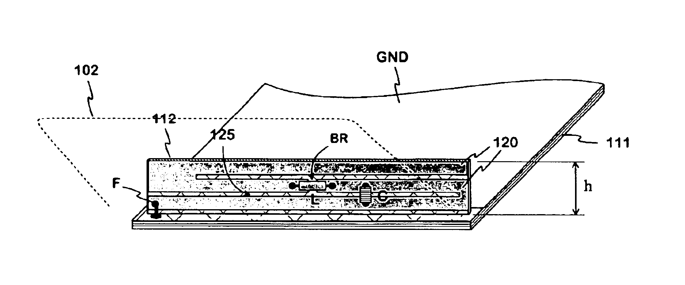
[0014]FIG. 1 shows an example of an antenna according to the invention. The figure shows a circuit board 111 in a foldable radio device, the upper surface of which circuit board mainly being a conductive ground plane GND. The circuit board is included in a first part of the foldable radio device. The figure also shows in broken line a second part 102 of the foldable radio device in the opened position. At one end of the circuit board of the radio device is an oblong antenna circuit board 112. The antenna circuit board is supported on the the radio device circuit board with a long side against the latter so that said circuit boards are in right angles with respect to each other. The radiating element in the antenna is a conductive strip 120 on the antenna circuit board. The plane of the radiating element is thus perpendicular to the ground plane, which is essential in the invention. The conductive strip 120 is situated on the outer surface of the antenna circuit board, i.e. on that s...


PUM


Abstract

A small and foldable radio device antenna and a radio device which has an antenna according to an embodiment of the invention. The radiating element in the antenna is a conductor having an outline shaped substantially like a rectangle and defining a plane which is perpendicular to the ground plane situated on the circuit board of the radio device. The radiating element fits inside the foldable device in the perpendicular position. The element is connected to the radio device only by its feed point. Resonating frequencies of the element can be arranged by shaping the element, and by means of discrete components. The matching of the antenna is arranged by providing an appropriate distance between the radiating element and ground plane. In an operating situation, an antenna gain is achieved which is considerably higher than that of a PIFA of equal height.

Description

[0001]The invention relates to an antenna intended to be used in a small and foldable radio device. The invention also relates to a radio device which has an antenna according to the invention.BACKGROUND OF THE INVENTION[0002]Commercial portable radio devices, such as mobile phones, include some foldable, i.e. clamshell models. These have got two parts such that the parts can be folded over, on a hinge, so that they lie on top of each other or adjacently end-to-end in almost the same plane. In the first, closed-up, position, the device is particularly small, and in the latter, opened, position the device is used during communication.[0003]Antennas used in foldable mobile phones are normally monopole-type external antennas. Their drawback is the impracticality generally associated with a protruding structural element. Naturally it would be possible to use internal PIFA-type planar antennas, but the thin structure of the folding parts in the mobile phone would result in the distance b...

Claims


Application Information

Patent Timeline
IPC IPC(8): H01Q5/00H01Q9/42H01Q1/36H01Q1/38H01Q9/04H01Q1/24H01Q5/321
CPCH01Q1/242H01Q1/36H01Q5/321H01Q9/42H01Q1/38
Inventor ANNAMAA, PETTERIMIKKOLA, JYRKIOLLITERVO, PETRA
Owner CANTOR FITZGERALD SECURITIES
Why Eureka
Try Eureka