System for performing ellipsometry using an auxiliary pump beam to reduce effective measurement spot size

a technology of ellipsometry and auxiliary pump, applied in the field of ellipsometry systems, can solve the problems of chromatic aberration, limit reduction of measurement spot size, and inability to reduce measurement size, etc., and achieve the effect of effective small measurement spo

Inactive Publication Date: 2005-10-04
THERMA WAVE INC
View PDF7 Cites 20 Cited by
  • Summary
  • Abstract
  • Description
  • Claims
  • Application Information

AI Technical Summary

Benefits of technology

[0011]An aspect of the present invention provides an ellipsometer that produces an effectively small measurement spot even when operating at large angles of incidence. For a representative implementation, the ellipsometer includes a first illumination source that creates a probe beam. The probe beam may be monochromatic or, more typically, polychromatic. The probe beam is passed through a first polarizer that imparts a known polarization state to the probe beam. The polarized probe beam is then directed to reflect from the sample. The angle of incidence between the incoming probe beam and the sample is implementation dependent. In most cases, this angle will be non-zero and may be relatively large (e.g. seventy-degrees). The reflected probe beam passes through a rotating compensator (if present) and then through a second polarizer (analyzer).

Problems solved by technology

At the same time, it is not always practical to reduce measurement size, particularly for ellipsometers.
Chromatic aberration is a second obstacle that often limits reductions in measurement spot sizes for ellipsometers.
Chromatic aberration results when an optical system transports light in a wavelength dependent fashion.
At the same time, the use of multiple angles of incidence increases the difficulty (i.e., computational complexity) of interpreting the resulting measurements.
In some cases, this can make this particular approach impractical.
At the same time, the use of normal or near normal incidence has a tendency to reduce or eliminate the distinction between p and s polarized light and may make this approach unsuitable for some applications.

Method used


Image

  • System for performing ellipsometry using an auxiliary pump beam to reduce effective measurement spot size
  • System for performing ellipsometry using an auxiliary pump beam to reduce effective measurement spot size

Examples


Embodiment Construction

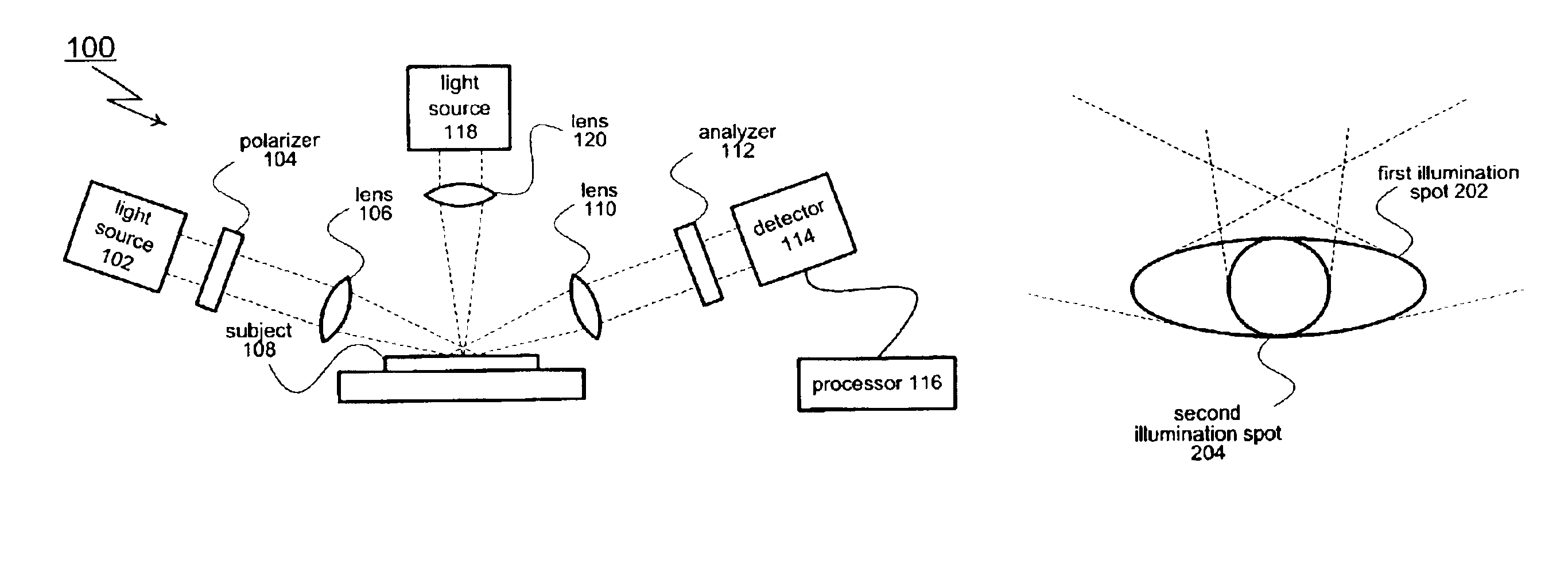
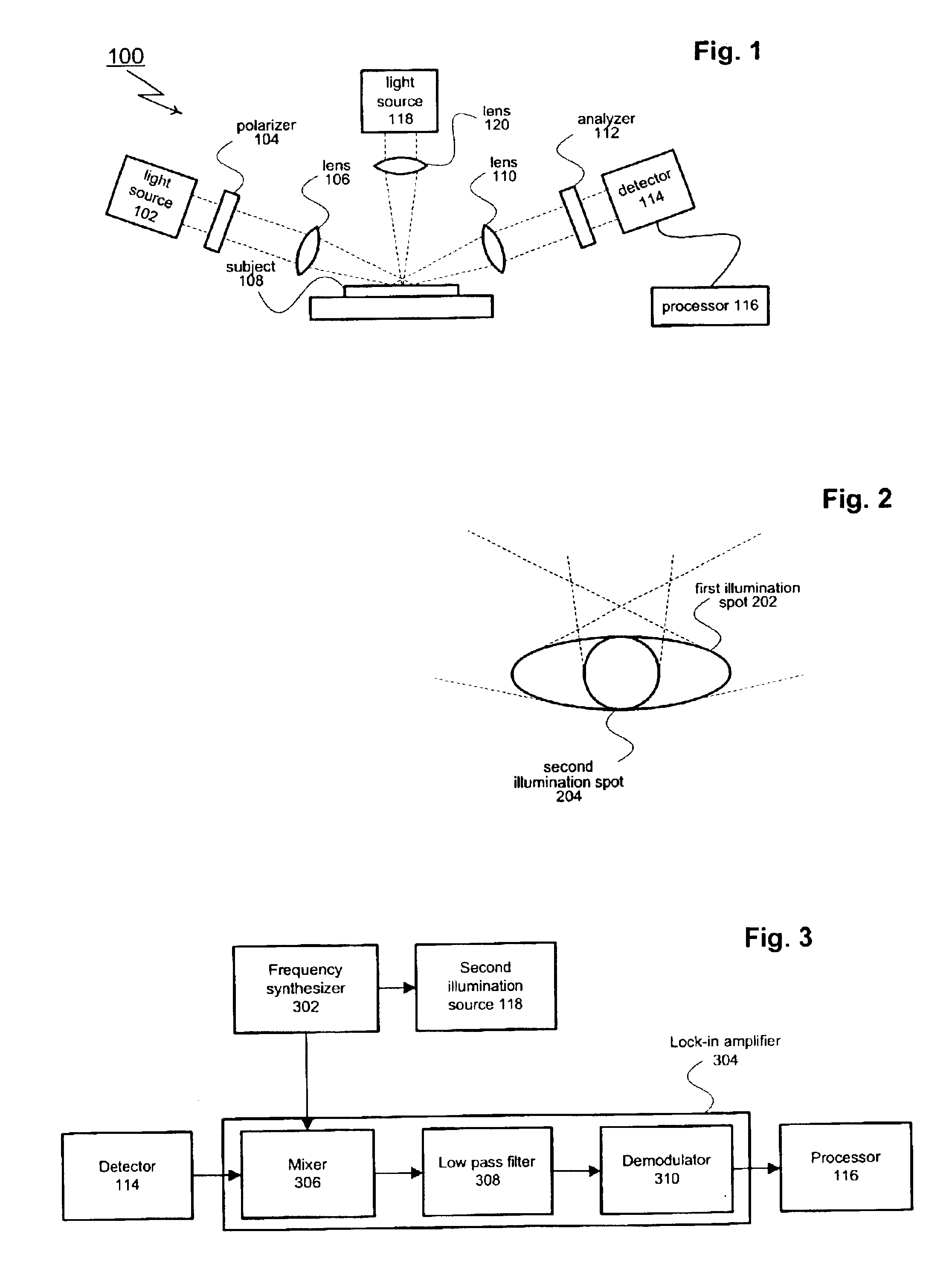
[0017]As shown in FIG. 1, an aspect of the present invention includes an ellipsometer generally designated 100. Ellipsometer 100 includes a first illumination source 102 that creates a mono or polychromatic probe beam. The probe beam is passed through a polarizer 104 and focused by one or more lenses 106 (or other appropriate optical elements such as mirrors). Polarizer 104 imparts a known polarization state to the probe beam. The polarized probe beam creates an illumination spot on the surface of the subject under test 108. An image of the illumination spot (or a portion of the illumination spot) passes through one or more lenses 110 and an analyzer 112 before reaching a detector 114. Lenses 110 may be selected from a range of different components including achromatic lenses and focusing mirrors. Detector 114 captures (or otherwise processes) the received image. A processor 116 analyzes the data collected by the detector 114.

[0018]Ellipsometer 100 also includes a second illuminatio...


PUM

PropertyMeasurementUnit
angle of incidenceaaaaaaaaaa
reflectivityaaaaaaaaaa
polarityaaaaaaaaaa

Abstract

An ellipsometer includes a light source for generating a probe beam of polychromatic light for interacting with a sample. The probe beam is passed through a first polarizer that imparts a known polarization state to the probe beam. The polarized probe beam is then directed to reflect from the sample. A second illumination source is switched on and off at a predetermined frequency to create an intensity modulated pump beam (the beam may also be chopped). The pump beam is directed normally against the subject producing a small illumination spot within the area illuminated by the probe beam. The pump induces localized changes in the dielectric properties of the subject. The pump-beam induced oscillations are picked up by the portion of the probe beam that is reflected from within the illumination spot of the pump beam. By analyzing only the portion of the reflected probe beam that includes the pump beam induced oscillation, the size of the measurement spot is effectively limited to the illumination spot size of the normally directed pump beam.

Description

TECHNICAL FIELD[0001]The subject invention relates to ellipsometry systems used to inspect and analyze semiconductor wafers. In particular, this invention relates to ellipsometry systems that operate using small measurement spot sizes.BACKGROUND OF THE INVENTION[0002]As geometries continue to shrink, manufacturers have increasingly turned to optical techniques to perform non-destructive inspection and analysis of semi-conductor wafers. The basis for these techniques is the notion that a subject may be examined by analyzing the reflected energy that results when a probe beam is directed at the subject. Ellipsometry and reflectometry are two examples of commonly used optical techniques. For the specific case of ellipsometry, changes in the polarization state of the probe beam are analyzed. Reflectometry is similar, except that changes in magnitude of the reflected intensities are analyzed. Scatterometry is a related technique that measures the diffraction (optical scattering) that the...

Claims


Application Information

Patent Timeline
Patent Type & Authority Patents(United States)
IPC IPC(8): G01N21/21G01N21/88G01N21/95G01J4/00
CPCG01J4/00G01N21/211G01N21/9501
Inventor EBERT, MARTIN
Owner THERMA WAVE INC
Why Eureka
Try Eureka