
Power module

a power module and power technology, applied in the direction of cooling/ventilation/heating modification, semiconductor/solid-state device details, semiconductor devices, etc., can solve the problems of poor heat transition between the electronic components of the circuit arrangement and the cooling body, negative influence of heat conductivity, and difficult dissipation of the dissipation power etc., to achieve sufficient heat dissipation of the electronic components, small thermal resistance, and high reliability and useful life of the power modul

Inactive Publication Date: 2005-10-04
VITESCO TECH GERMANY GMBH
View PDF22 Cites 19 Cited by
  • Summary
  • Abstract
  • Description
  • Claims
  • Application Information

AI Technical Summary

Benefits of technology

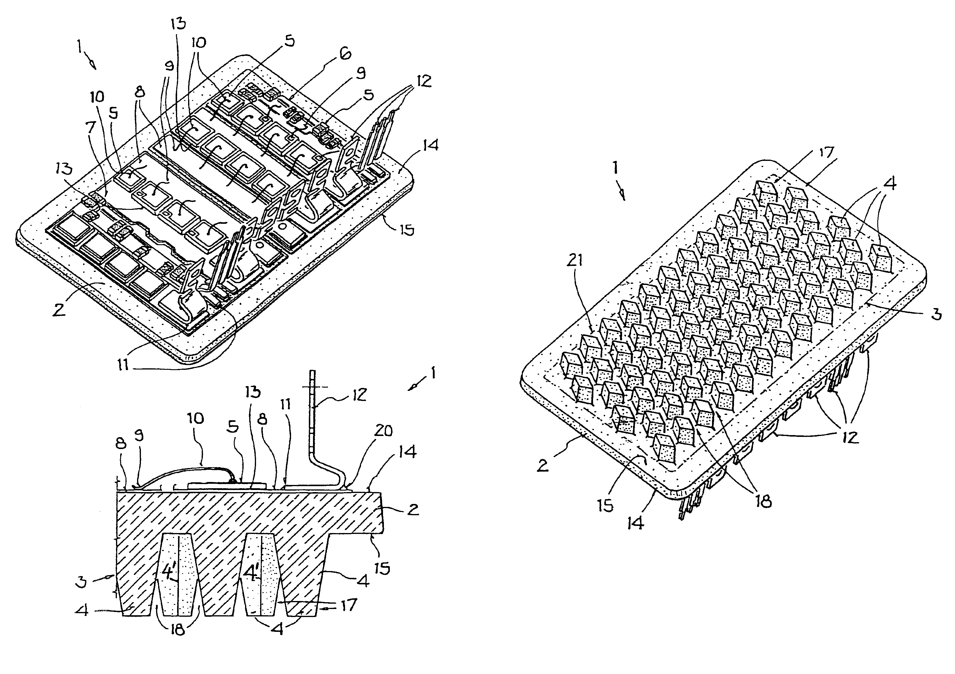
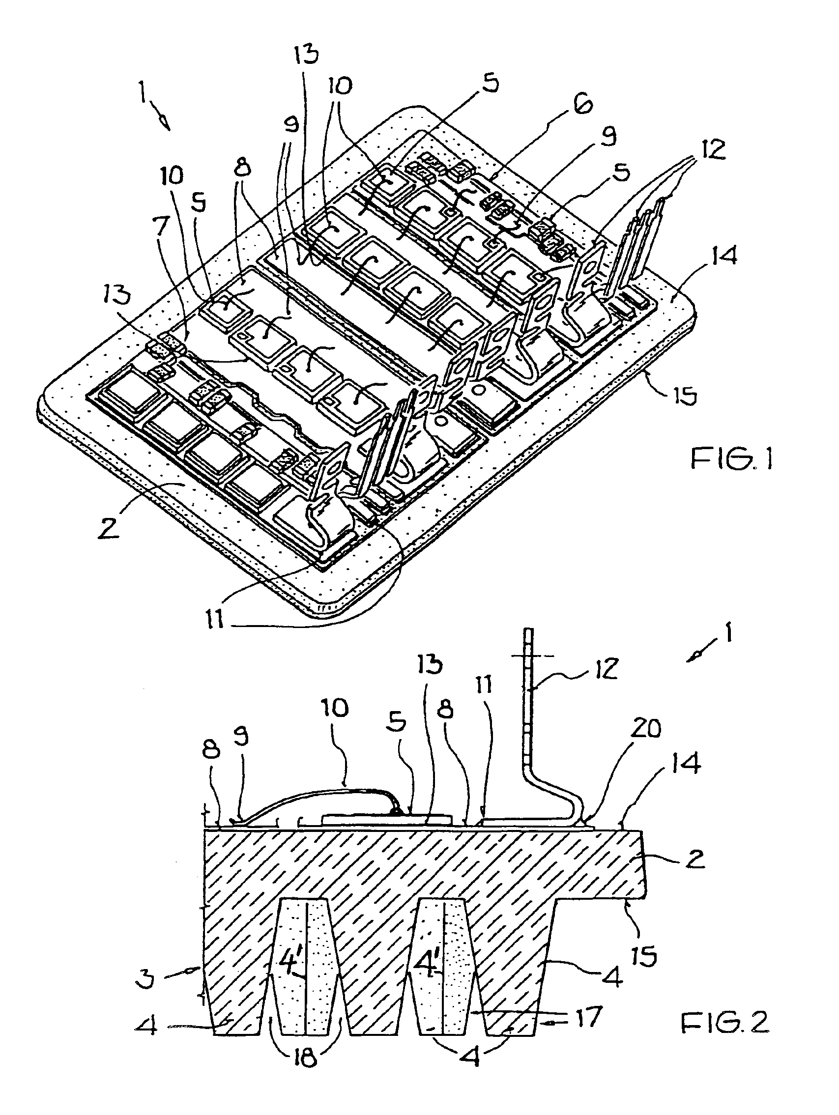
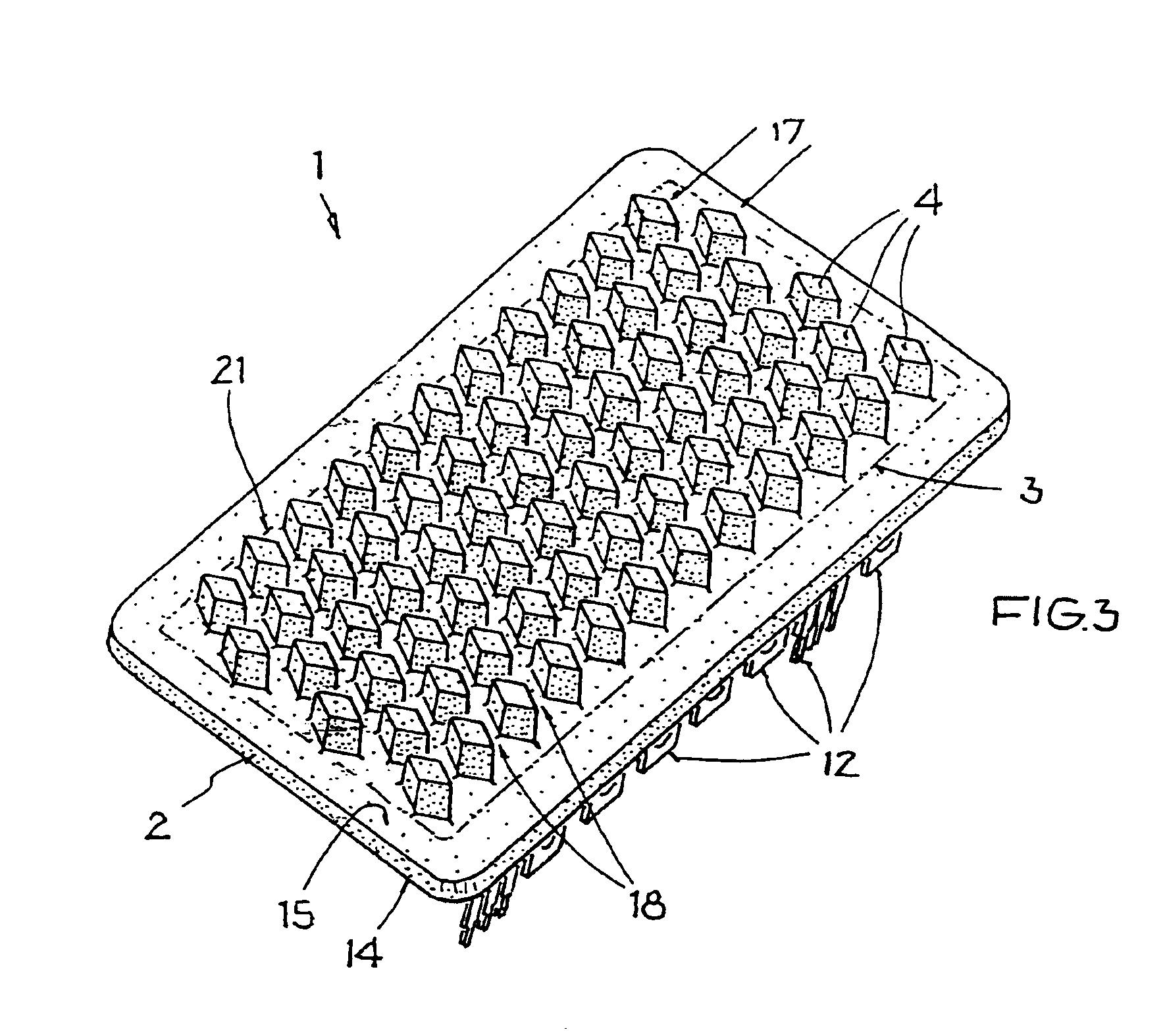
[0011]The power module combines several advantages. The carrier body serves for the heat dissipation and as a circuit carrier or substrate for the electronic components of the circuit arrangement. The carrier body also serves as a seal when the power module is directly arranged in a cooling circuit and thus it serves for the integration of the array of the geometric cooling members into the cooling circuit. By the direct mounting of the electronic components of the circuit arrangement on the carrier body and by the direct connection of the geometric cooling members to the carrier body without any intermediate layers a small thermal resistance is obtained, whereby thermal problems can be avoided so that a high reliability and useful life of the power module are achieved. By preselecting the structure of the geometric cooling members a sufficient heat dissipation of the electronic components of the circuit arrangement is assured, particularly a variably selectable heat dissipation can be achieved by a respective shaping of the geometric cooling members of the cooling element so that particularly in connection with an integration of the cooling element into the cooling circuit of a cooling system the through-flow velocity of the coolant and the pressure loss in the cooling circuit can be adapted to the requirements. The production effort and expense is small because a simple production of the cooling element with its geometric cooling members is possible, particularly when the carrier body and the geometric cooling members are made in a single production step in the same tool. Thereby, manufacturing problems can be avoided which entails small manufacturing costs, particularly also due to the use of simple and low cost materials.

Problems solved by technology

The thick bonding layer causes a high heat resistance particularly due to inclusions in the bonding layer such as shrink holes in a solder layer, which negatively influence the heat conductivity.
Thus, a poor heat transition exists between the electronic components of the circuit arrangement and the cooling body due to the heat resistances that are formed by the inclusions.
As a result, the dissipation of the dissipation power of the electronic components becomes difficult.
On the other hand, the connection between the carrier body and the cooling body is frequently impaired, whereby the life duration and thus the reliability of the power modules is significantly reduced.

Method used


Image

  • Power module
  • Power module
  • Power module

Examples


Embodiment Construction

[0016]The power module 1 is for example used as a power converter for liquid cooled electric motors in the field of motor vehicles where a power of for example 10 kW is generated or used. Due to the occurring high dissipation power the power converter 1 is coupled directly to the liquid cooling flow of the electric motor, i.e. it is integrated into the cooling circuit of the electrical motor whereby a coolant such as water flows through the cooling circuit.

[0017]The power converter 1 comprises a carrier body 2 as a circuit carrier formed, for example as a ceramic substrate or ceramic carrier made of, for example aluminum nitride (AlN). The body 2 has for example the dimensions of 90 mm×57 mm×3 mm. The carrier body 2 is directly integrated into the cooling circuit and thus takes over the sealing of the cooling circuit relative to the further components of the power converter 1.

[0018]A conductor structure 7 having a thickness of, for example 0.3 mm is applied to the top side or surfac...


PUM


Abstract

A power module is suggested having a simple and cost-effective arrangement and ensuring a reliable operation. To this end, a circuit arrangement comprising at least one electronic component is arranged on a carrier body. A conductor pattern is formed on the top side of the carrier body, and a structured cooling element made of the material of the carrier body, is provided on the bottom side. The invention also relates to a power module as power converter for electric motors.

Description

FIELD OF THE INVENTION[0001]Electronic modules are used in many areas for different objectives and applications. Electronic modules constructed as power modules are used particularly for control purposes, for example for the closed loop control of the r.p.m. and of the power of electric motors.BACKGROUND INFORMATION[0002]Electronic components for providing the required power are part of such power modules. For example, in connection with electric motors the power is typically in the kilowatt range. Power modules are used for providing control signals and / or for the evaluation of measured signals. As a rule, the active and passive components of the circuit arrangement of such power module require a construction that has a low inductance to avoid excess voltages. Active components include, for example, power components that are working in a switching operation at high speed current changes, particularly integrated switching circuits operating as power switches. Passive components incl...

Claims


Application Information

Patent Timeline
Patent Type & Authority Patents(United States)
IPC IPC(8): H01L23/13H01L23/34H01L23/373H01L23/367H01L23/12
CPCH01L23/13H01L23/3677H01L23/3735H01L2224/48227H01L2224/48465H01L2224/73265H01L2924/01004H01L2924/01013H01L2924/01029H01L2924/19041H01L2924/30107H01L24/48H01L2924/00H01L2924/10253H01L2224/05599H01L2224/45099H01L2224/85399H01L2924/00014H01L2924/181H01L2224/49113H01L2224/0603H01L2924/19105H01L2224/45015H01L2924/207
Inventor BAEUMEL, HERMANNGRAF, WERNERKILIAN, HERMANNSCHUCH, BERNHARD
Owner VITESCO TECH GERMANY GMBH
Learn More