Microfabricated fluidic circuit elements and applications

a fluidic circuit and micro-fabricated technology, applied in the field of micro-fabricated fluidic systems, can solve the problems of large number of macroscopic control lines, inability to provide sufficient force by itself, and insufficient control of numerous on-chip valves of previously known on-chip systems

Inactive Publication Date: 2005-10-11
FLUIDIGM CORP
View PDF16 Cites 75 Cited by
  • Summary
  • Abstract
  • Description
  • Claims
  • Application Information

AI Technical Summary

Benefits of technology

[0009]It is therefore an object of the present invention to provide pressure sources and control lines that control the opening and closing of valves on-chip so that macroscopic control lines exiting the chip are minimized or eliminated.
[0010]It is also an object of the present invention to provide numerous microfabricated fluidic switches on-chip that open and close channels without the need for large pressure differentials.

Problems solved by technology

In complex assays, a large number of macroscopic control lines is cumbersome and undesirable.
Previously known electrical actuating devices have not been able to provide sufficient force by themselves to open or close a fluidic valve.
Previously known on-chip systems have not been adequate to provide control of numerous on-chip valves.
Numerous valves coupled together to perform complex functions would require very large pressure differentials to drive all of the cascaded valves.
Pressure sources that generate such very high pressure differentials are difficult to manufacture on a microfabricated chip.
Furthermore, such cascaded valve systems do not allow for the introduction of feedback elements.

Method used


Image

  • Microfabricated fluidic circuit elements and applications
  • Microfabricated fluidic circuit elements and applications
  • Microfabricated fluidic circuit elements and applications

Examples


first embodiment

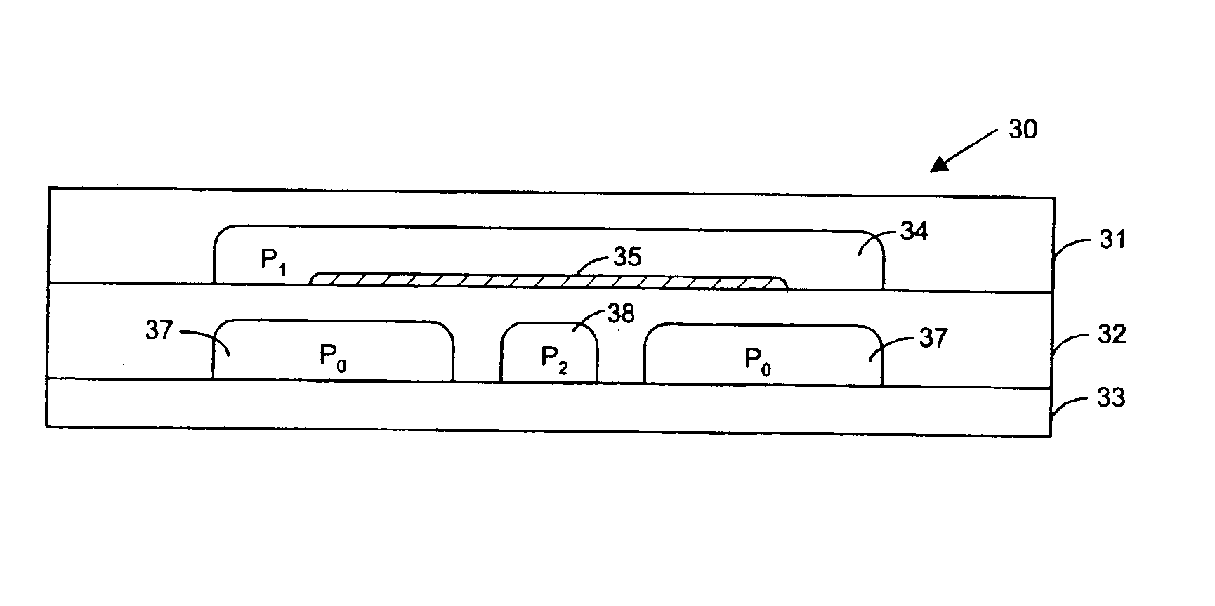
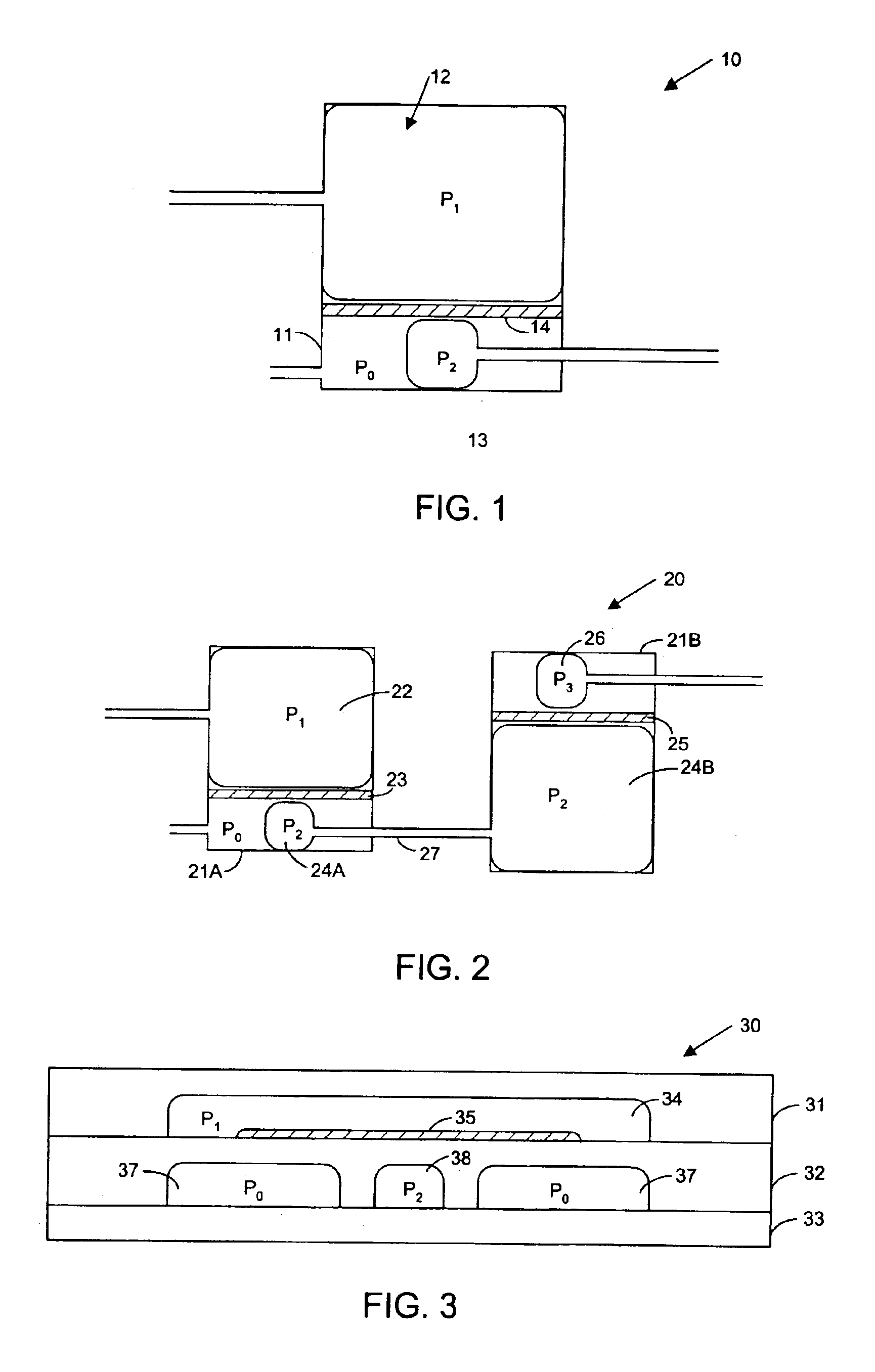
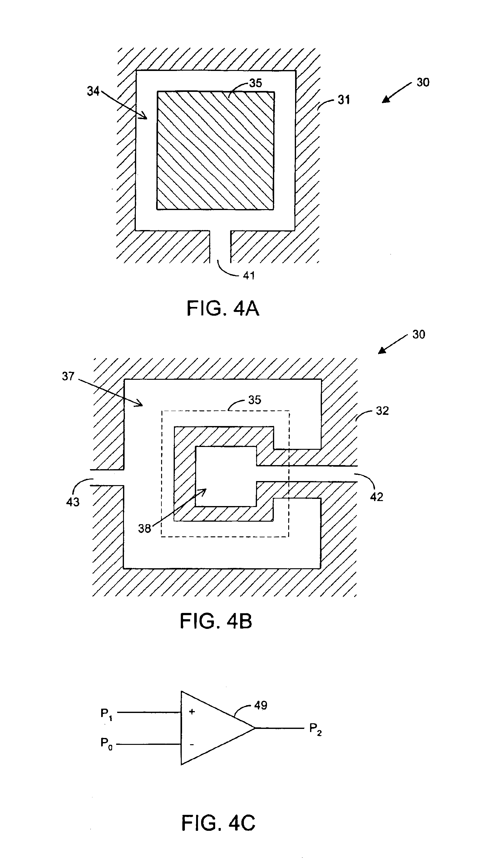
[0078]a microfabricated fluidic pressure amplifier (or pressure multiplier) of the present invention is shown in FIGS. 3, 4A and 4B. Pressure multiplier 30 shown in FIG. 3 is a cross sectional view of a microfabricated fluidic pressure amplifier that contains pre-cured elastomer layers 31 and 32 that are formed on top of rigid planar substrate 33 (e.g., glass). There are many, many types of elastomeric polymers. Common elastomeric polymers that may be used to form elastomer layers 31-32 and other elastomer layers of the present invention include polyisoprene, polybutadiene, polychloroprene, polyisobutylene, poly(styrene-butadiene-styrene), the polyurethanes, and silicones.

[0079]Layer 31 has chamber 34, and layer 32 has chambers 37-38. Layers 31-32 and other elastomer layers used to form microfluidic devices of the present invention may be formed and hermetically sealed together using methods discussed in further detail in Microfabricated Elastomeric Valve and Pump Systems, PCT Paten...

second embodiment

[0100]a microfabricated fluidic switch is shown in FIGS. 7A-7E. FIGS. 7A-7D are cross sectional views of fluidic switch 70, and FIG. 7E is a top down view of fluidic switch 70. FIGS. 7A and 7C are cross sectional views along channel 74, and FIGS. 7B and 7D are cross sectional views along horizontal axis 77 illustrated in FIG. 7E. Switch 70 includes substrate 73, elastomer layer 72, and elastomer layer 71. Elastomer layer 71 contains channel 74, and elastomer layer 72 contains channel 78 and chambers 79A and 79B. Channel 74 is coupled to the gate of the switch. Channel 78 is coupled between the source and the drain of the switch. Layers 71-73 may be formed and hermetically sealed using methods described in further detail in PCT Patent Application Number PCT / US / 00 / 17740 mentioned above.

[0101]Layer 75 comprises a rigid material (such as PMMA) that is deposited on top of layer 72. Layer 71 can then be placed on top of layer 72 so that layer 75 is inside channel 74. Layer 75 is deposited...

third embodiment

[0111]a microfabricated fluidic switch is shown in FIG. 8. Fluidic switch 80 comprises substrate 83 and elastomer layers 81 and 82. FIG. 8 is a cross sectional view of switch 80 across channel 84. Channel 84 is coupled to the gate of the switch. Layer 82 comprises channel 88 and chambers 89A and 89B. Channel 88 is coupled between the drain and the source of the switch. Rigid material 85 is deposited inside region 86 and on top of layer 82 as shown in FIG. 8.

[0112]When pressure P1 in channel 84 increases, rigid layer 85 moves downwardly, closing channel 88. The extension of rigid layer 85 into region 86 facilitates the closing of channel 88 by more effectively concentrating the force applied by layer 85 directly over drain-to-source channel 88. Chambers 89A-89B allow channel 88 to be closed without having to increase the pressure in gate channel 84 above the pressure in channel 88. Therefore, switch 80 may be coupled with other microfluidic switches to perform logic functions and oth...


PUM


Abstract

The present invention provides microfabricated fluidic systems and methods. Microfabricated fluidic devices of the present invention include switches that can be opened and closed to allow or block the flow of fluid through a channel in response to the pressure level in a gate of the switch. The microfabricated fluidic switches may be coupled together to perform logic functions and Boolean algebra, such as inverters, AND gates, NAND, gates, NOR gates, and OR gates. The logic gates may be coupled together to form flip-flops that latch signals. The present invention also includes microfabricated fluidic pressure multipliers that increase the pressure in a second chamber relative to a first chamber. Microfabricated fluidic devices of the present invention also include pressure sources. A pressure source of the present includes a pump coupled to a reservoir through unidirectional valves. The pressure source may be high pressure source or a low pressure source. Microfabricated fluidic devices of the present invention may also include devices that perform analog functions such as switching regulator.

Description

CROSS-REFERENCES TO RELATED APPLICATIONS[0001]This application is a division of U.S. Application Ser. No. 09 / 995,397, filed Nov. 26, 2001 now U.S. Pat. No. 6,802,342, which claims the benefit of U.S. Provisional Patent Application No. 60 / 282,253, filed Apr. 6, 2001, which are both incorporated by reference herein.BACKGROUND OF THE INVENTION[0002]The present invention relates to microfabricated fluidic systems and methods for regulating the flow of fluid to provide switches, logic gates, latches, pressure sources, analog devices, capacitors, unidirectional valves, pressure multipliers, and devices that perform mathematical functions.[0003]Microfabricated fluidic chips may be used for biological assays. For example, microfabricated fluidic chips may be used to perform biological assays using external control lines that control the opening and closing of on-chip fluidic valves. The on-chip fluidic valves control the flow of fluids in biological assays. The valves are opened and closed ...

Claims


Application Information

Patent Timeline
Patent Type & Authority Patents(United States)
IPC IPC(8): B01L3/00F15C3/04F15C5/00F15C3/00G06F17/50F16K99/00
CPCB01L3/502707B01L3/50273B01L3/502738F15C3/04F16K99/0001F16K99/0009F16K99/0015F16K99/0059G06F17/509F15C3/00A61M2206/22B01L2200/0621B01L2200/14B01L2300/123B01L2400/0487B01L2400/0638B01L2400/0655F16K99/0034F16K2099/0074F16K2099/008F16K2099/0082F16K2099/0084G06F2217/16H01H2029/008Y10T137/2224Y10T137/7892Y10T137/2202Y10T137/7891Y10T137/7879Y10T137/2218Y10T137/206G06F30/18G06F2111/10F16K15/16F16K15/147
Inventor FERNANDES, DAVID N.CHOU, HOU-PUUNGER, MARC A.
Owner FLUIDIGM CORP
Why Eureka
Try Eureka