

Centrifugal fan
a centrifugal fan and fan body technology, applied in the direction of machines/engines, stators, liquid fuel engines, etc., can solve the problems of increasing the noise, affecting the efficiency of the centrifugal fan, and the blade passing frequency (bpf) is severe, so as to reduce the noise
- Summary
- Abstract
- Description
- Claims
- Application Information
AI Technical Summary
Benefits of technology
Problems solved by technology
Method used
Image

Examples
first embodiment
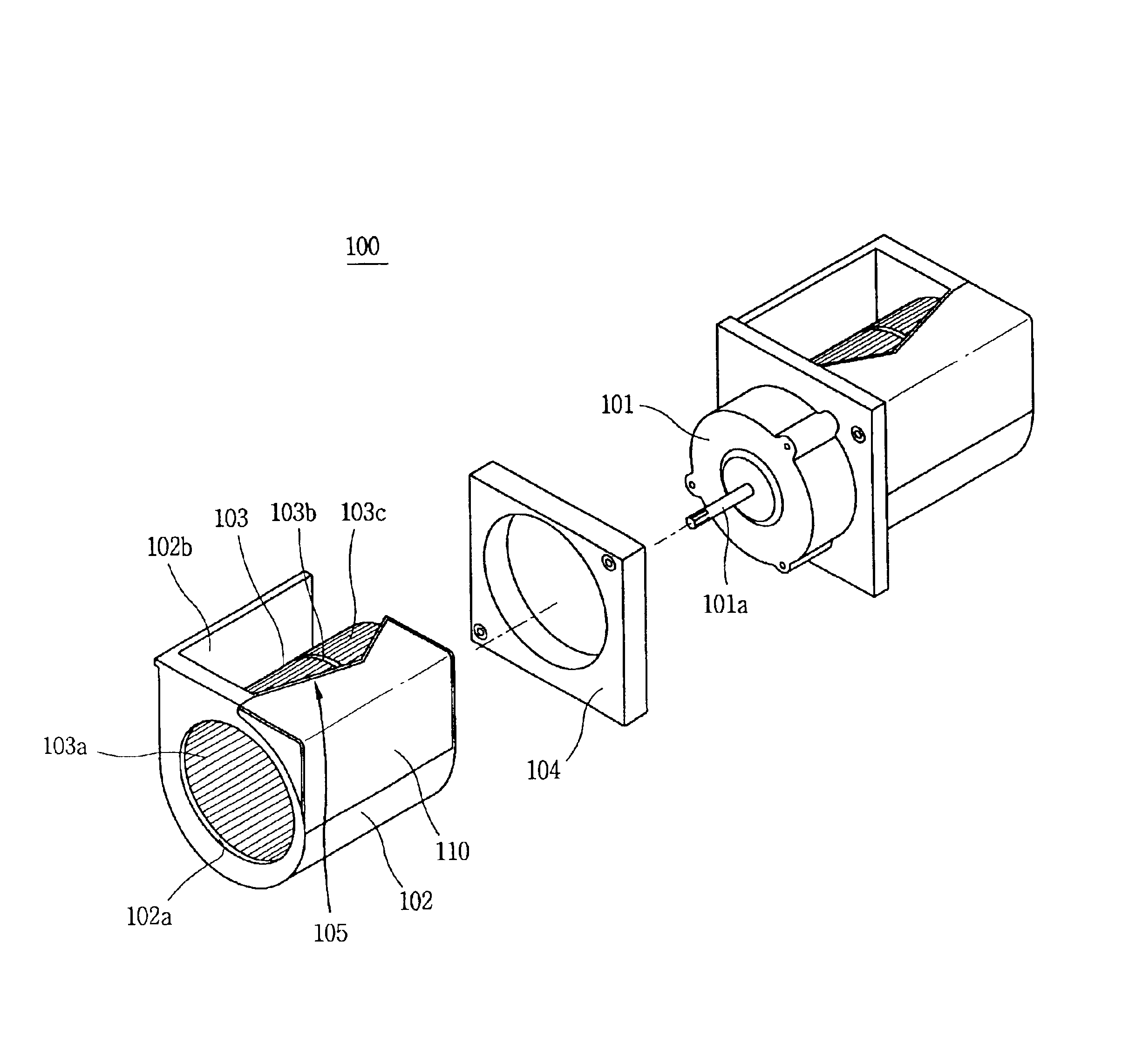
[0077]The cut-off portion 105 is weak in terms of its structure, causing a severe noise. In order to solve this problem, a sound insulating plate 110 is formed as a noise transmission blocking and structure reinforcing unit to cover the outer side of the housing 102 at an end of the cut-off portion 105 in accordance with the present invention.
[0078]A space (S) may be formed between the sound insulating plate 110 and the housing 102 or may not be formed therebetween. In terms of light weight of the overall centrifugal fan 100, it is preferred to have a space.
[0079]The sound insulating plate 110 can be fabricated as a separate member for the housing 102, and preferably is integrally formed with the housing in order to improve its rigidity.
[0080]The sound insulating plate 110 can be formed in various shapes. As shown in FIG. 6, the sound insulating plate 110 can be in a clamp shape to cover a portion of the outer side of the housing 102, or as shown in FIGS. 7 and 8, it can be formed i...
second embodiment
[0089]Meanwhile, in case of the general centrifugal fan, in the aspect of its structure, air sucked through the air suction opening is orbited by about 90° to be discharged through the air discharge opening, during which a vortex is generated at the inner side of the housing. In order to prevent generation of the vortex, a guide member is installed to guide air sucked through the air suction opening toward the air discharge opening in accordance with the present invention.
[0090]The second embodiment of the present invention will now be described with reference to FIGS. 10 to 12.
[0091]FIG. 10 is a perspective view showing a centrifugal fan in accordance with a second embodiment of the present invention, FIG. 11 is a cross section view taken along section line a-a′, b-b′, c-c′ of FIG. 10, FIG. 12 is a perspective view showing a first guide member of FIG. 10, and FIG. 13 is a partial perspective view showing a second guide member of FIG. 10.
[0092]As shown in FIG. 10, a centrifugal fan ...
third embodiment
[0114]FIG. 17 is an exploded perspective view showing a centrifugal fan in accordance with the present invention.
[0115]As illustrated, a centrifugal fan 300 in accordance with the third embodiment of the present invention includes a passage recess 304a formed at the inner side of a motor bracket 304 adjacent to an air discharge opening 302a in order to minimize a BPF noise and flow noise of air being discharged toward an air discharge opening 302a. The passage recess 304a is formed to be gradually widened as it goes toward the air discharge opening 302a, and the inner side thereof is formed rounded.
[0116]In the case that the passage recess 304a is formed at the inner side of the motor bracket 304, when the centrifugal fan operates, air introduced into the housing 302 through the air suction opening 302a is smoothly discharged along the passage recess 304a toward the air discharge opening 302a. Since the air is smoothly discharged through the air discharge opening 302a, no vortex is ...
PUM
 Abstract
Description
Claims
Application Information