
Safety device to limit pressure in an axial-piston compressor housing

a safety device and compressor technology, applied in the direction of machines/engines, positive displacement liquid engines, lighting and heating apparatus, etc., can solve the problems of inability to continue the compressor operation, in case of loss of refrigeran

Inactive Publication Date: 2005-10-11
LUK FAHRZEUG HYDRAULIK +1
View PDF14 Cites 13 Cited by
  • Summary
  • Abstract
  • Description
  • Claims
  • Application Information

AI Technical Summary

Benefits of technology

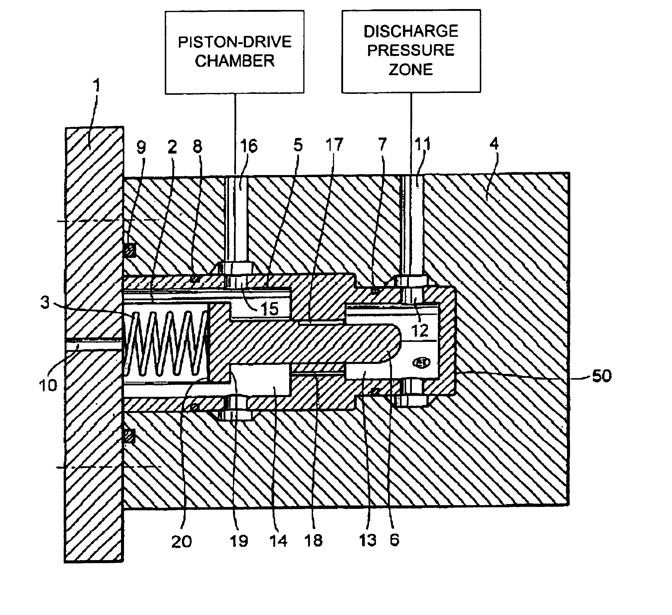
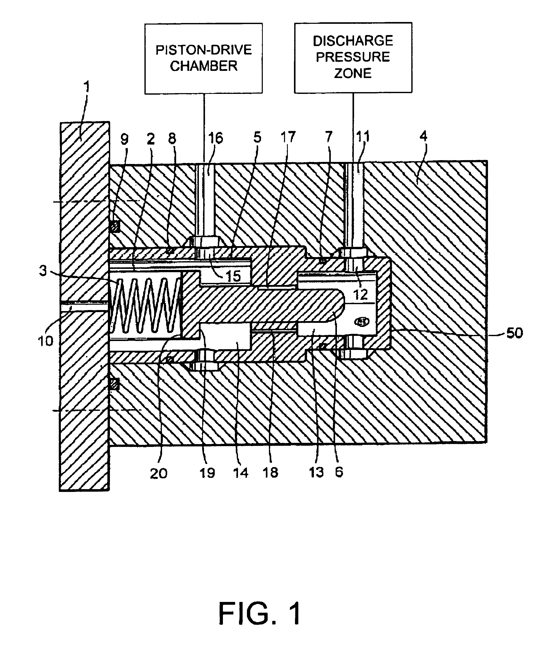
[0004]In view of the drawbacks inherent in safety devices for air-conditioning compressors of the prior art, the invention has the objective of providing an improved safety device to protect the air-conditioning compressor against overpressure in the high-pressure zone.
[0011]The invention has the particular advantages that the compressor can continue to operate after a response action of the pressure-limiting device and that no refrigerant medium is released to the ambient environment.

Problems solved by technology

In particular with burst discs, continued operation of the compressor is impossible because the burst disc is destroyed by the excess pressure.
With pressure-limiting valves, there is in any case a loss of refrigerant because a part of the refrigerant in the air-conditioning system is released to the ambient environment.

Method used


Image

  • Safety device to limit pressure in an axial-piston compressor housing
  • Safety device to limit pressure in an axial-piston compressor housing

Examples


Embodiment Construction

[0016]In the embodiment of a safety device shown in FIG. 1, a valve housing 5 is installed in a housing portion 4 which can be formed by a part of a compressor housing. The valve housing 5 contains a movable valve piston 6 that is pushed into the closed valve position by a spring 3. The spring compartment of the spring 3 is sealed off from the rest of the valve compartment by a bellows 2 that is arranged between the valve piston 6 and a cover plate 1. The spring compartment of the spring 3 shares the ambient pressure outside the air-conditioning compressor through an opening 10 in the cover plate 1. The valve housing 5 is sealed against the housing portion 4 by O-ring seals 7 and 8. As is self-evident, other sealing arrangements could be used to accomplish the same effect. The cover plate 1 is likewise sealed against the housing portion 4 by a seal 9. A connection, shown in FIG. 1 as a channel bore through the housing portion 4, runs from the discharge pressure zone 11 of the compre...


PUM


Abstract

A safety device limits the pressure in an axial-piston compressor with variable piston displacement. The compressor has as wobble plate or swash plate whose tilt angle can be variably controlled by the pressure differential between the high pressure in the discharge pressure zone and the pressure in the piston-drive chamber. The safety device consists of a valve arranged in a connector channel between the discharge pressure zone and the pressure zone of the piston-drive chamber. When the discharge pressure exceeds a given pressure limit, the safety device responds by allowing an increased flow of pressure medium from the discharge pressure zone to the piston-drive chamber. The influx of pressure medium into the piston-drive chamber causes a reduction of the tilt angle of the swash plate or wobble plate.

Description

[0001]This is a continuation of international application Ser. No. PCT / DE01 / 02388, filed Jun. 27, 2001, the entire disclosure of which is hereby incorporated by reference.BACKGROUND OF THE INVENTION[0002]The invention relates to a safety device for limiting the high pressure in the discharge pressure zone of an air-conditioning compressor with a variable piston stroke or displacement volume. The compressor is of the type known as wobble plate piston pump or swash plate piston pump, wherein the angle of the wobble plate or swash plate can be variably controlled by the pressure differential between the high pressure in the discharge pressure zone and the pressure in the piston-drive chamber, or in some cases by the pressure differential between the piston-drive chamber and the suction pressure zone of the air-conditioning compressor. Compressors of this type therefore have a connector channel that connects the outlet chamber in the discharge pressure zone to the pressure zone of the p...

Claims


Application Information

Patent Timeline
Patent Type & Authority Patents(United States)
IPC IPC(8): F04B27/18F04B27/14F04B27/10B60H1/32F04B49/10F25B1/00
CPCF04B27/1036F04B27/1081F04B27/1804F04B2027/185F04B2027/1872F04B2027/189F04B2027/1895Y10T137/7939Y10T137/7849F16K15/025
Inventor WEBER, GEORGSICKELMANN, MICHAELSCHAFER, TILOWALTER, CHRISTOPHKRAUSS, HANS-JOACHIMRAISER, HARALDOBRIST, FRANK
Owner LUK FAHRZEUG HYDRAULIK
Learn More