Total feed forward switching power supply control

a technology of power supply control and forward switching, applied in the direction of process and machine control, ignition automatic control, instruments, etc., can solve the problems of largely impracticality, and achieve the effect of accurate mapping and accurate control of output voltag

Active Publication Date: 2005-10-11
INFINEON TECH AMERICAS CORP
View PDF10 Cites 71 Cited by
  • Summary
  • Abstract
  • Description
  • Claims
  • Application Information

AI Technical Summary

Benefits of technology

[0012]If the transfer function of a power supply relative to its several inputs can be accurately mapped, it is possible to set the duty factor of the power supply according to the values of these inputs and achieve accurate control of output voltage.

Problems solved by technology

While this total feed forward approach is entirely possible with analog circuitry, it is largely impractical due to the necessary complexity and cost.

Method used


Image

  • Total feed forward switching power supply control
  • Total feed forward switching power supply control
  • Total feed forward switching power supply control

Examples


Embodiment Construction

[0023]By employing digital control in the form of a microcontroller, microprocessor, DSP (Digital Signal Processor), logic state machine or other digital implementation (processor), combined with mixed signal circuitry for acquisition of inputs, it is possible to achieve a practical implementation of this technique.

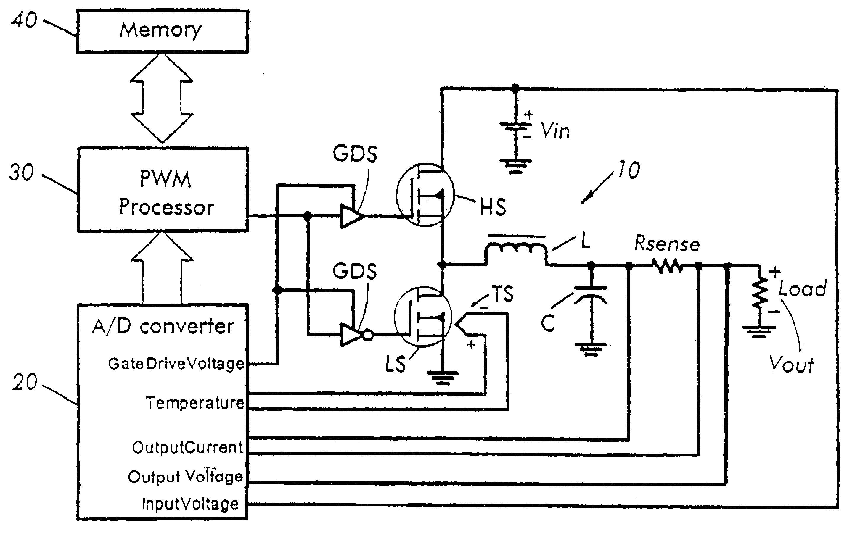
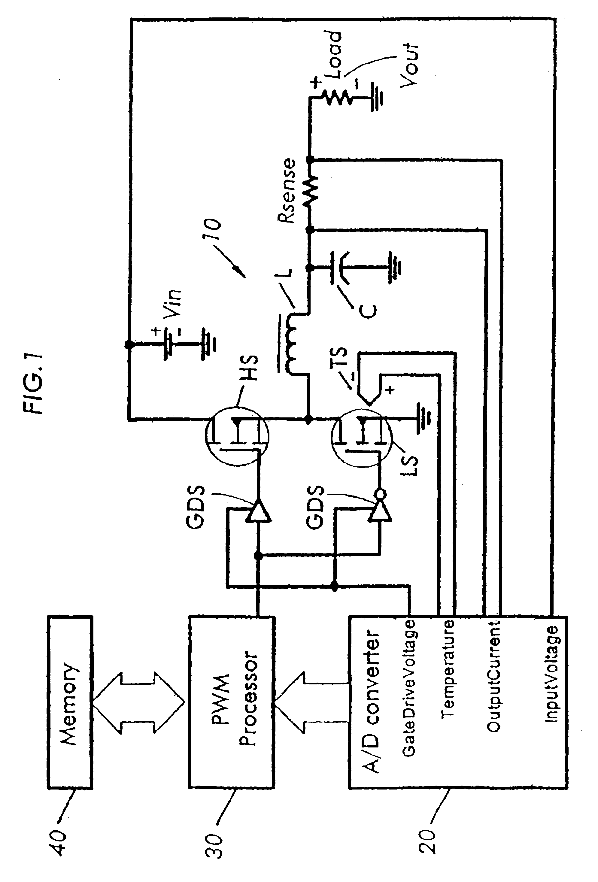
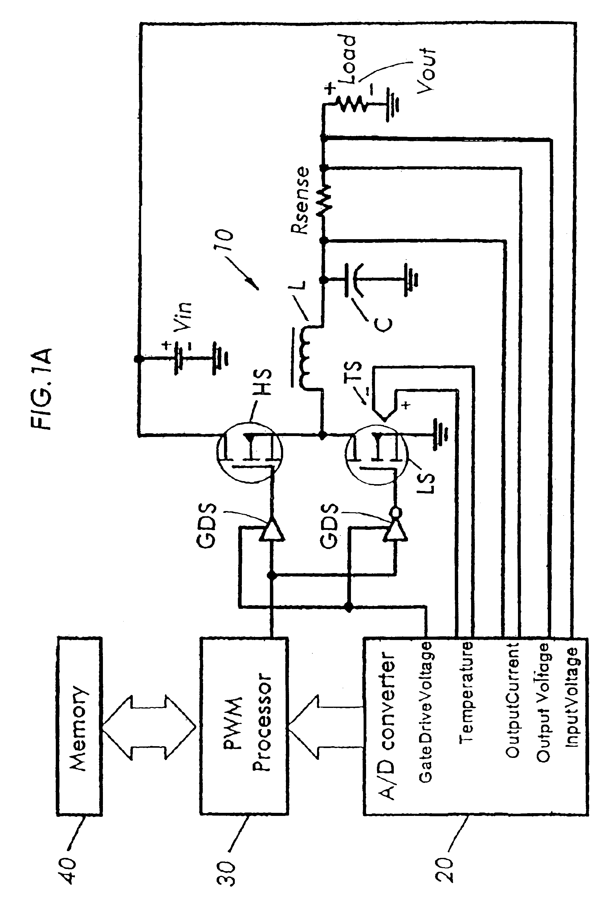
[0024]With reference now to FIG. 1, the power supply converter 10 can be any switching power supply topology, e.g., buck, boost, buck / boost, flyback, etc. A buck converter topology is shown including high side (HS) and low side (LS) switches, output inductor L and output capacitor C. The DC bus is indicated by voltage Vin. This control method is theoretically valid for any topology, but will be most effective when employed in synchronous rectification topologies in which the output is not a function of storage inductance value under light load. Gate drive voltage sensors (GDS) are provided for sensing the gate drive voltages of the switches. A temperature sensor (TS) may ...


PUM


Abstract

A power supply comprising a switching converter capable of being controlled by a control signal to provide a desired output from a DC input voltage, an analog to digital converter receiving as analog inputs a gate drive voltage of at least one switch of the switching converter, a temperature related measurement of the switching converter, the DC input voltage and an output current of the switching converter and converting the analog inputs to digital input signals, a digital processor receiving the digital input signals and generating the control signal to drive at least one switch of the switching converter to drive the output of the switching converter to the desired output and a memory storing data relating the digital input signals to the desired output of the switching converter and providing to the digital processor a memory output signal to enable the processor to generate the control signal to drive the at least one switch to provide the desired output from the switching converter.

Description

CROSS REFERENCE TO RELATED APPLICATIONS[0001]This application claims the priority and benefit of U.S. Provisional Application Ser. No. 60 / 515,325, filed Oct. 29, 2003 entitled TOTAL FEED FORWARD SWITCHING POWER SUPPLY CONTROL and U.S. Provisional Application Ser. No. 60 / 512,349 filed Oct. 17, 2003 entitled TOTAL FEED FORWARD SWITCHING POWER SUPPLY CONTROL, the entire disclosures of each of which are incorporated by reference herein.BACKGROUND OF THE INVENTION[0002]Traditional switching power supplies use feedback compared to an internal reference in order to control the output to within a specified range. From a DC standpoint this is ideal since the output is actually controlled to the desired accuracy. From an AC / transient standpoint this is less than ideal because of the finite time required to respond to an “input” change.[0003]In this case “input” refers to any one of the factors that can affect output voltage of the power supply, including:[0004]Input voltage;[0005]Power switch...

Claims


Application Information

Patent Timeline
Patent Type & Authority Patents(United States)
IPC IPC(8): G05F1/56G05F1/10H02M3/335H02M3/24
CPCH02M3/158H02M2001/0019H02M2001/0022H02M1/0019H02M1/0022
Inventor BROWN, JAMES STEVEN
Owner INFINEON TECH AMERICAS CORP
Why Eureka
Try Eureka