Balanced-unbalanced converting circuit and laminated balanced-unbalanced converter

a technology of unbalanced converting circuit and laminated converter, which is applied in the direction of electrical equipment, multiple-port networks, waveguides, etc., can solve the problems of increasing circuit size, increasing insertion loss, increasing circuit elements, etc., and achieves better spurious signal suppression, reduce the thickness and reduce the size of the balanced-unbalanced converter

Active Publication Date: 2005-10-11
MURATA MFG CO LTD
View PDF3 Cites 30 Cited by
  • Summary
  • Abstract
  • Description
  • Claims
  • Application Information

AI Technical Summary

Benefits of technology

[0014]With this structure, spurious signals, such as second and third harmonics, are reliably eliminated and minimized, thus achieving a desirable attenuation characteristic.
[0016]Each of the first balanced terminal and the second balanced terminal may be electrically connected with a device for adjusting the imaginary part of the impedance of the LC parallel resonant circuit, resulting in easy impedance adjustment. Such devices may be, for example, strip lines (coils).
[0017]According to a preferred embodiment of the present invention, furthermore, in the laminated balanced-unbalanced converter, the first and second strip lines may be provided on the same layer and the third and fourth strip lines may be provided on the same layer, and the first and second strip lines face the third and fourth strip lines via the dielectric layer. The thickness of the balanced-unbalanced converter can therefore be reduced.
[0018]According to a preferred embodiment of the present invention, furthermore, the laminate preferably includes a first trap circuit electrically connected with a first balanced terminal and a second trap circuit electrically connected with a second balanced terminal. Each of the first trap circuit and the second trap circuit includes an LC parallel resonant circuit having a coil. First and second capacitors are disposed between the first, second, third, and fourth strip lines and the coils of the first and second trap circuits in the lamination direction of the laminate. With this structure, capacitor electrodes of the first and second capacitors, which occupy large portions of the same dielectric layer, prevent magnetic coupling between the first, second, third, and fourth strip lines and the first and second trap circuits. Therefore, the size of the balanced-unbalanced converter can be reduced without deteriorating the insertion loss and the attenuation characteristic.

Problems solved by technology

This increases the circuit size, the number of circuit elements, and the insertion loss.
The balun circuit 11 shown in FIG. 9 has the LC parallel resonant circuits 12 to 15, and therefore requires a large number of elements, resulting in increased insertion loss.

Method used


Image

  • Balanced-unbalanced converting circuit and laminated balanced-unbalanced converter
  • Balanced-unbalanced converting circuit and laminated balanced-unbalanced converter
  • Balanced-unbalanced converting circuit and laminated balanced-unbalanced converter

Examples


first preferred embodiment

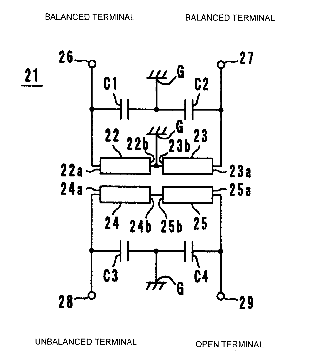
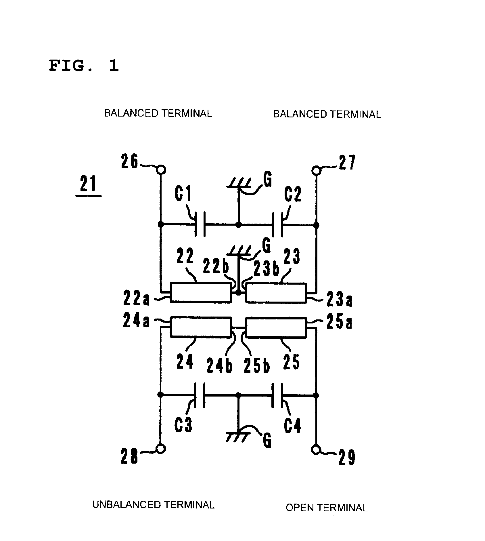
[0031]A balun circuit 21 according to a first preferred embodiment of the present invention will be described with reference to FIGS. 1 and 2. As shown in FIG. 1, the balun circuit 21 includes strip lines 22, 23, 24, and 25 of a quarter wavelength or less. The strip lines 22, 23, 24, and 25 have first ends 22a, 23a, 24a, and 25a, and second ends 22b, 23b, 24b, and 25b, respectively. The first end 22a of the strip line 22 is electrically connected with a balanced terminal 26, and the second end 22b thereof is electrically connected with a ground terminal G. The first end 23a of the strip line 23 is electrically connected with a balanced terminal 27, and the second end 23b thereof is electrically connected with the ground terminal G. The first end 24a of the strip line 24 is electrically connected with an unbalanced terminal 28, and the second end 24b thereof is electrically connected with the second end 25b of the strip line 25. The first end 25a of the strip line 25 is electrically ...

second preferred embodiment

[0038]A balun circuit 41 according to a second preferred embodiment of the present invention will be described with reference to FIGS. 3 and 4. The balun circuit 41 shown in FIG. 3 is different from the balun circuit 21 shown in FIG. 1 in that a trap circuit 44 is electrically connected between the balanced terminal 26 and the strip line 22 and a trap circuit 45 is electrically connected between the balanced terminal 27 and the strip line 23. The trap circuit 44 is an LC parallel resonant circuit having a capacitor C5 and a coil (strip line) 42. The trap circuit 45 is preferably an LC parallel resonant circuit having a capacitor C6 and a coil (strip line) 43.

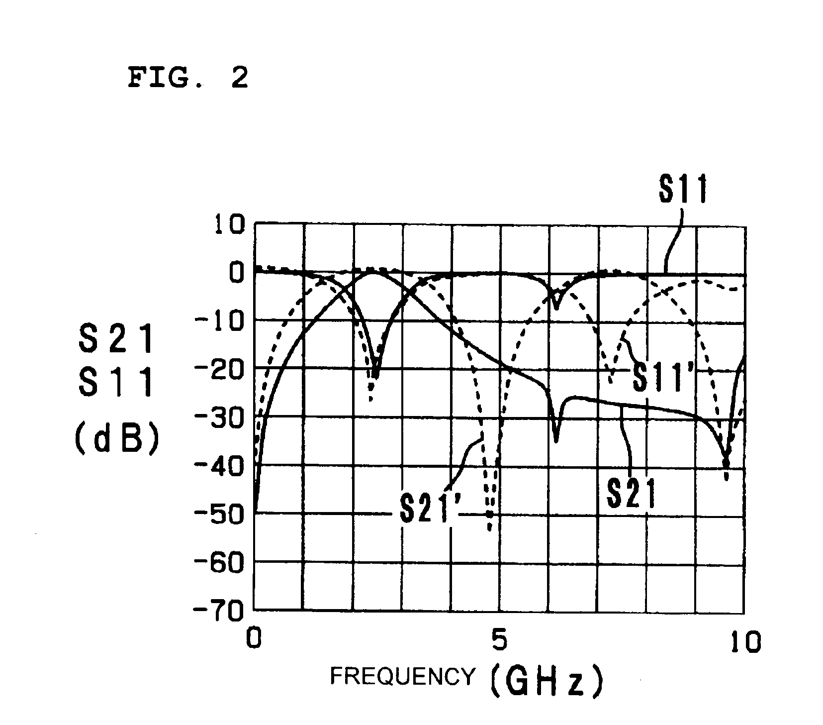
[0039]FIG. 4 is a graph showing the transmission (S21) characteristic and input reflection (S11) characteristic of the balun circuit 41, as indicated by solid lines S21 and S11, respectively. For the sake of comparison, FIG. 4 also shows the transmission (S21′) characteristic and input reflection (S11′) characteristic of the bal...

third preferred embodiment

[0040]A balun circuit 51 according to a third preferred embodiment of the present invention will be described with reference to FIGS. 5 to 7. The balun circuit 51 shown in FIG. 5 is different from the balun circuit 41 shown in FIG. 3 in that a coil (strip line) 52 is electrically connected between the balanced terminal 26 and the trap circuit 44 and a coil (strip line) 53 is electrically connected between the balanced terminal 27 and the trap circuit 45 in order to adjust the imaginary part of the impedance of the trap circuit 44 and 45, respectively. These coils allow for easy impedance adjusting of the trap circuits 44 and 45. Specifically, the longer the line lengths of the coils 52 and 53 to increase the inductance, the higher the imaginary part of the impedance; the shorter the line lengths of the coils 52 and 53 to reduce the inductance, the lower the imaginary part of the impedance.

[0041]FIG. 6 is an exploded perspective view of a laminated balun converter 51A incorporating t...


PUM


Abstract

A balanced-unbalanced converting circuit includes first to fourth strip lines of a quarter wavelength or less. The first strip line has an end connected with a balanced terminal, and the third strip line has an end connected with an unbalanced terminal. The end of the first strip line connected to the balanced terminal opposes the end of the third strip line connected to the unbalanced terminal so that the first and third strip lines are electromagnetically coupled so as to define a coupler. The second strip line has an end connected with a balanced terminal, and the fourth strip line has an end connected with an open terminal. The end of the second strip line connected to the balanced terminal opposes the end of the fourth strip line connected to the open terminal so that the second and fourth strip lines are electromagnetically coupled so as to define a coupler.

Description

BACKGROUND OF THE INVENTION[0001]1. Field of the Invention[0002]The present invention relates to a balanced-unbalanced converting (balun) circuit and a laminated balanced-unbalanced converter.[0003]2. Description of the Related Art[0004]Generally, merchant or marchand baluns and transformer baluns having a filter for use at high frequencies, such as microwave frequencies, are known. A merchant balun is described in, for example, Japanese Unexamined Patent Application Publication No. 9-260145.[0005]FIG. 8 shows a balun circuit 1 of this type having strip lines 2 to 5. The strip line 2 is electrically connected between a balanced terminal 6 and a ground terminal G, and the strip line 3 is electrically connected between a balanced terminal 7 and the ground terminal G. The strip lines 4 and 5 are electrically connected in series between an unbalanced terminal 8 and an open terminal 9. The strip lines 2 and 4 are opposed to each other in such a manner that a first end 2a of the strip lin...

Claims


Application Information

Patent Timeline
Patent Type & Authority Patents(United States)
IPC IPC(8): H01P5/10H03H7/00H03H7/42
CPCH03H7/422H01P5/10
Inventor NOSAKA, KOJI
Owner MURATA MFG CO LTD
Why Eureka
Try Eureka